Nissan Rogue Service Manual: Removal and installation
FRONT COMBINATION LAMP
Exploded View
- Front fender
- Front combination lamp
 Clip
Clip
Removal and Installation
REMOVAL
- Remove front bumper fascia. Refer to EXT-17, "Removal and Installation".
- Remove front combination lamp bolts and clip.
- Pull front combination lamp forward.
- Disconnect the harness connectors from the front combination lamp and remove.
INSTALLATION
Installation is in the reverse order of removal.
NOTE: After installation, perform headlamp aiming adjustment. Refer to EXL-114, "Inspection".
Bulb Replacement
WARNING: Do not touch bulb by hand while it is lit or right after being turned off. Burning may result.
CAUTION:
- Do not touch the glass surface of the bulb with bare hands or allow oil or grease to get on it to prevent damage to the bulb.
- Do not leave bulb out of lamp reflector for a long time because dust, moisture smoke, etc. may affect the performance of lamp. When replacing bulb, be sure to replace it with new one.
HEADLAMP (LOW BEAM) BULB
Removal
- Rotate the bulb counterclockwise and remove from the front combination lamp.
- Disconnect the harness connector from bulb and remove.
Installation
Installation is in the reverse order of removal.
CAUTION: After installing the bulb, install the bulb socket securely for watertightness.
HEADLAMP (HIGH BEAM) BULB
Removal
- Remove plastic cover.
- Rotate the bulb counterclockwise and remove from the front combination lamp.
- Disconnect the harness connector from bulb and remove.
Installation
Installation is in the reverse order of removal.
CAUTION: After installing the bulb, install the bulb socket securely for watertightness.
PARKING (SIDE MARKER) LAMP BULB
Removal
- Rotate the bulb counterclockwise and remove from the front combination lamp.
- . Remove the bulb from the bulb socket.
Installation
Installation is in the reverse order of removal.
CAUTION: After installing the bulb, install the bulb socket securely for watertightness.
TURN SIGNAL LAMP BULB
Removal
- Rotate bulb socket counterclockwise and remove from the front combination lamp.
- Remove the bulb from bulb socket.
Installation
Installation is in the reverse order of removal.
CAUTION: After installing the bulb, install the bulb socket securely for watertightness.
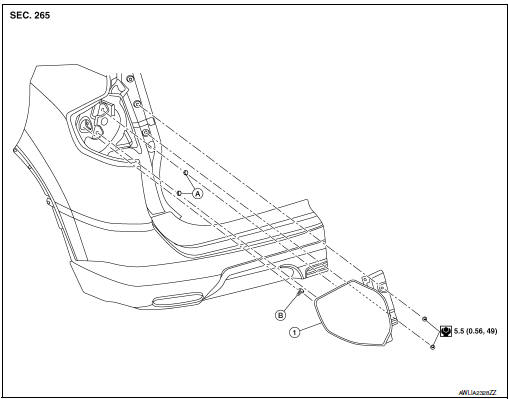
FOG LAMP
Exploded View
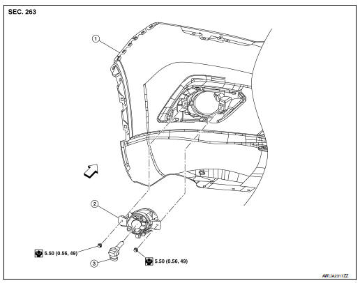
- Front bumper fascia
- Fog lamp
- Fog lamp bulb
 Front
Front
Removal and Installation
REMOVAL
- Partially remove front fender protector. Refer to EXT-28, "FENDER PROTECTOR : Exploded View".
- Disconnect the harness connector from the fog lamp.
- Remove fog lamp bolts and fog lamp.
INSTALLATION
Installation in the reverse order of removal.
NOTE: After installation, perform fog lamp aiming adjustment. Refer to EXL-117, "Aiming Adjustment Procedure".
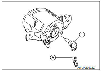
Bulb Replacement
WARNING: Do not touch bulb by hand while it is lit or right after being turned off. Burning may result.
CAUTION:
- Do not touch the glass surface of the bulb with bare hands or allow oil or grease to get on it to prevent damage to the bulb.
- Do not leave bulb out of lamp reflector for a long time because dust, moisture smoke, etc. may affect the performance of lamp. When replacing bulb, be sure to replace it with new one.
REMOVAL
- Partially remove front fender protector. Refer to EXT-28, "FENDER PROTECTOR : Exploded View".
- Disconnect the harness connector from the fog lamp (A).
- Rotate bulb (1) counterclockwise and remove.
INSTALLATION
Installation is in the reverse order of removal.
CAUTION: After installing the bulb, install the bulb socket securely for watertightness.
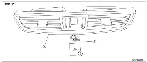
OPTICAL SENSOR
Removal and Installation
REMOVAL
- Release the optical sensor (2) from defroster grille (1) using a suitable tool.
- Disconnect the harness connector (A) from the optical sensor (2) and remove.
INSTALLATION
Installation is in the reverse order of removal.
COMBINATION SWITCH
Exploded View
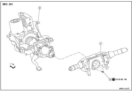
- Combination switch
- Steering column
- Screw
 Front
Front
Removal and Installation
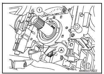
REMOVAL
- Remove the steering angle sensor. Refer to BRC-139, "Removal and Installation".
- Disconnect harness connector from combination switch.
- Remove screw (A) and combination switch (1).
INSTALLATION
Installation is in the reverse order of removal.
HAZARD SWITCH
Exploded View
- Center ventilator grille
- Hazard switch
 Pawl
Pawl
Removal and Installation
REMOVAL
- Remove center ventilator grille. Refer to VTL-13, "CENTER VENTILATOR GRILLE : Removal and Installation".
- Release the pawls and remove the hazard switch.
INSTALLATION
Installation is in the reverse order of removal.
SIDE TURN SIGNAL LAMP
Removal and Installation
REMOVAL
- Remove door mirror rear finisher. Refer to MIR-25, "Removal and Installation".
- Remove door mirror glass. Refer to MIR-24, "Removal and Installation".
- Remove the screws (A) and reposition side turn signal lamp.
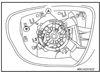
- Disconnect the harness connector from the side turn signal lamp and remove.
INSTALLATION
Installation is in the reverse order of removal.
Bulb Replacement
The side turn signal lamp bulb is not serviced separately. Refer to EXL-126, "Removal and Installation".
REAR COMBINATION LAMP
Exploded View
- Rear combination lamp
- Grommet
- Clip
Removal and Installation
REMOVAL
- Remove side air spoiler. Refer to EXT-48, "Removal and Installation".
- Remove rear combination lamp bolts.
- Pull rear combination lamp rearward to release from clip and locators.
- Disconnect the harness connector from the rear combination lamp and remove.
INSTALLATION
Installation is in the reverse order of removal.
Bulb Replacement
WARNING: Do not touch bulb with bare hand while it is lit or right after being turned off. Burning may result.
CAUTION:
- Do not touch the glass surface of the bulb with bare hands or allow oil or grease to get on it to prevent damage to the bulb.
- Do not leave bulb out of lamp reflector for a long time because dust, moisture smoke, etc. may affect the performance of lamp. When replacing bulb, be sure to replace it with new one.
STOP LAMP BULB
Removal
- Remove rear combination lamp. Refer to EXL-127, "Removal and Installation".
- Rotate stop lamp bulb socket counterclockwise and remove.
- Remove stop lamp bulb from bulb socket.
Installation
Installation is in the reverse order of removal.
CAUTION: After installing the bulb, install bulb socket securely for watertightness.
TAIL LAMP BULB
Removal
- Remove rear combination lamp. Refer to EXL-127, "Removal and Installation".
- Rotate tail lamp bulb socket counterclockwise and remove.
- Remove tail lamp bulb from bulb socket.
Installation
Installation is in the reverse order of removal.
CAUTION: After installing the bulb, install bulb socket securely for watertightness.
TURN SIGNAL LAMP BULB
Removal
- Remove rear combination lamp. Refer to EXL-127, "Removal and Installation".
- Rotate turn signal lamp bulb socket counterclockwise and remove.
- Remove turn signal lamp bulb from bulb socket.
Installation
Installation is in the reverse order of removal.
CAUTION: After installing the bulb, install bulb socket securely for watertightness.
HIGH-MOUNTED STOP LAMP
Exploded View
- High-mounted stop lamp
- Back door
 Stud
Stud
Removal and Installation
REMOVAL
- Remove access cover using a suitable tool. Refer to INT-38, "Exploded View".
- Remove high-mounted stop lamp nuts.
- Disconnect the harness connector from high-mounted stop lamp and remove.
INSTALLATION
Installation is in the reverse order of removal.
Bulb Replacement
HIGH-MOUNTED STOP LAMP BULB
The high-mounted stop lamp bulb is not serviced separately. Refer to EXL-129, "Removal and Installation".
BACK-UP LAMP ASSEMBLY
Exploded View
- Back-up lamp assembly
- Back door
 Clip
Clip
 Stud
Stud
Removal and Installation
REMOVAL
- Remove back door finisher. Refer to INT-38, "Removal and Installation".
- Remove back-up lamp assembly nuts.
- Pull back-up lamp assembly rearward, disconnect the harness connector and remove.
INSTALLATION
Installation is in the reverse order of removal.
Bulb Replacement
WARNING: Do not touch bulb with bare hand while it is lit or right after being turned off. Burning may result.
CAUTION:
- Do not touch the glass surface of the bulb with bare hands or allow oil or grease to get on it to prevent damage to the bulb.
- Do not leave bulb out of lamp reflector for a long time because dust, moisture smoke, etc. may affect the performance of lamp. When replacing bulb, be sure to replace it with new one.
TAIL LAMP BULB
Removal
- Remove back-up lamp assembly. Refer to EXL-130, "Removal and Installation".
- Rotate tail lamp bulb socket counterclockwise and remove.
- Remove tail lamp bulb from bulb socket.
Installation
Installation is in the reverse order of removal.
CAUTION: After installing the bulb, install bulb socket securely for watertightness.
BACK-UP LAMP BULB
Removal
- Remove back-up lamp assembly. Refer to EXL-130, "Removal and Installation".
- Rotate back-up lamp bulb socket counterclockwise and remove.
- Remove back-up lamp bulb from bulb socket.
Installation
Installation is in the reverse order of removal.
CAUTION: After installing the bulb, install bulb socket securely for watertightness.
LICENSE PLATE LAMP
Exploded View
- License plate lamp bulb
- License plate lamp seal
- License plate lamp
- License plate lamp assembly
- License plate lamp bulb socket
Removal and Installation
REMOVAL
- Release the license lamp finisher. Refer to EXT-50, "Exploded View".
- Remove the screw (A) (LH or RH) and pull license plate lamp (1) (LH or RH) downward.
- Disconnect the harness connector from the license plate lamp and remove.
INSTALLATION
Installation is in the reverse order of removal.
Bulb Replacement
WARNING: Do not touch bulb with your hand while it is on or right after being turned off. Burning may result.
CAUTION:
- Do not touch the glass surface of the bulb with bare hands or allow oil or grease to get on it to prevent damage to the bulb.
- Do not leave bulb out of lamp reflector for a long time because dust, moisture smoke, etc. may affect the performance of lamp. When replacing bulb, be sure to replace it with new one.
REMOVAL
- Remove license plate lamp. Refer to EXL-132, "Removal and Installation".
- Rotate license plate lamp bulb socket counterclockwise and remove.
- Remove license plate lamp bulb from bulb socket.
INSTALLATION
Installation is in the reverse order of removal.
CAUTION: After installing the bulb, install the bulb socket securely for watertightness.
 Periodic maintenance
HEADLAMP AIMING ADJUSTMENT
Inspection
PREPARATION BEFORE ADJUSTING
Before performing aiming adjustment, check the following:
Make sure all tires are inflated to correct pressure.
...
 Unit disassembly and assembly
FRONT COMBINATION LAMP
Exploded View
Front combination lamp
Parking (side marker) lamp bulb socket
Headlamp (low beam) bulb
Plastic cover
Headlamp (high beam) bulb
T ...
Other materials:
Component parts
Component Parts Location
A/C switch (auto A/C)
Front air control (manual A/C)
No.
Component
Description
1
Rear window defogger connector
(Rear window defogger)
Refer to DEF-5, "Rear window defogger".
2
3
Rear win ...
Preparation
Special Service Tool
The actual shape of the tools may differ from those illustrated here.
Tool number
(TechMate No.)
Tool name
Description
—
(J-46534)
Trim Tool Set
Removing trim components
Commercial Service Tools
Tool name
...
B142X collision detection
Description
DTC B1209 - B1211 COLLISION DETECTION
The air bag diagnosis sensor unit will set this DTC if it has detected a
collision which has resulted in a deployment
of one or more air bags or pre-tensioners. If this DTC is detected after a SRS
repair, the air bag diagnosis
sensor unit has ...
