Nissan Rogue Owners Manual: Push-Button Ignition Switch (if so equipped)
| WARNING Do not operate the push-button ignition switch while driving the vehicle except in an emergency. (The engine will stop when the ignition switch is pushed 3 consecutive times in quick succession or the ignition switch is pushed and held for more than 2 seconds.) If the engine stops while the vehicle is being driven, this could lead to a crash and serious injury. |
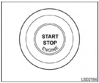
Push-Button Ignition Switch (if so equipped)
When the ignition switch is pushed without depressing the brake pedal, the ignition switch will illuminate.
Push the ignition switch center:
- once to change to ON.
- two times to change to OFF.
The ignition switch will automatically return to the LOCK position when any door is either opened or closed with the switch in the OFF position.
The ignition lock is designed so that the ignition switch position cannot be switched to OFF until the shift lever is moved to the P (Park) position.
When the ignition switch cannot be pushed toward the OFF position, proceed as follows:
- Move the shift lever into the P (Park) position.
- Push the ignition switch. The ignition switch position will change to the ON position.
- Push the ignition switch again to the OFF position.
The shift lever can be moved from the P (Park) position if the ignition switch is in the ON position and the brake pedal is depressed.
If the battery of the vehicle is discharged, the push-button ignition switch cannot be moved from the LOCK position.
Some indicators and warnings for operation are displayed on the vehicle information display. For additional information, refer to “Vehicle information display” in the “Instruments and controls” section of this manual.
- Operating range
- Push-button ignition switch positions
- NISSAN Intelligent Key® battery discharge (if so equipped)
- NISSAN vehicle immobilizer system
 Ignition switch (if so equipped)
WARNING
Never remove or turn the key to the
LOCK position while driving. The steering
wheel will lock (for models with a
steering lock mechanism). This may
cause the d ...
 Operating range
Operating range
The Intelligent Key functions can only be used
when the Intelligent Key is within the specified
operating range.
When the Intelligent Key battery is almost discharged
or str ...
Other materials:
Component parts
METER SYSTEM
METER SYSTEM : Component Parts Location
Vehicle front
View of the fuel pump and fuel level
sensor inspection hole covers with
the rear seat removed.
View of front engine assembly
No.
Component
Function
1
Combination me ...
Troubleshooting guide
Verify the location of all Intelligent Keys that are
programmed for the vehicle. If another Intelligent
Key is in range or inside the vehicle, the vehicle
system may respond differently than expected.
Symptom
Possible Cause
Remedy
When stopping the engine
The Shift to Pa ...
System description
VENTILATION SYSTEM
System Description
OUTLINE
Automatic A/C
The ventilation system is controlled by the A/C switch assembly. For details
of the automatic air conditioner
system, refer to HAC-10, "System Description".
Manual A/C
The ventilation system is controlled by the front air ...
