Nissan Rogue Service Manual: Component parts
METER SYSTEM
METER SYSTEM : Component Parts Location
 Vehicle front
- View of the fuel pump and fuel level sensor inspection hole covers with the rear seat removed.
- View of front engine assembly
|
No. |
Component |
Function |
| 1 | Combination meter | Refer to MWI-8, "METER SYSTEM : System Description". |
| 2 | Steering switch | Refer to MWI-18, "Switch Name and Function". |
| 3 | Meter control switch | Refer to MWI-18, "Switch Name and Function". |
| 4 | Fuel level sensor unit (sub) | Transmits the fuel level sensor signal to the combination meter. |
| 5 | Fuel level sensor unit (main) | Transmits the fuel level sensor signal to the combination meter |
| 6 | Seat belt buckle switch LH | Transmits the seat belt buckle switch signal LH to the combination meter. |
| 7 | ABS actuator and electric unit (control unit) |
|
| 8 | Engine oil pressure sensor | Transmits the engine oil pressure sensor signal to the ECM. |
| 9 | Washer fluid level switch |
|
| 10 | Ambient sensor |
|
| 11 | ECM |
|
| 12 | TCM |
|
| 13 | BCM |
|
| 14 | Parking brake switch | Transmits the parking brake switch signal to the combination meter. |
METER SYSTEM : Design
ARRANGEMENT OF COMBINATION METER
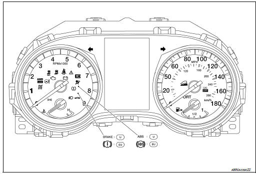
U: USA
EU: Except USA

 System
METER SYSTEM
METER SYSTEM : System Description
SYSTEM DIAGRAM
Combination Meter Input Signal (CAN Communication Signal)
DESCRIPTION
Combination Meter
The combination meter c ...
Other materials:
ABS actuator and electric unit (control unit)
Exploded View
ABS actuator and electric unit (control unit)
Connector
Bracket
To front LH brake caliper
To rear RH brake caliper
From master cylinder secondary side
From master cylinder primary side
To rear LH brake caliper
To front RH brake ...
Intelligent 4WD (if so equipped)
4X4–I SYSTEM OPERATION
WARNING
Do not drive beyond the performance
capability of the tires. Accelerating
quickly, sharp steering maneuvers or
sudden braking may cause loss of control,
even with Intelligent 4WD engaged.
For 4WD equipped vehicles, do not a ...
P0717 input speed sensor A
DTC Description
DTC DETECTION LOGIC
DTC
CONSULT screen terms
(Trouble diagnosis content)
DTC detection condition
P0717
INPUT SPEED SENSOR A
(Input/Turbine Speed Sensor “A” Circuit No
Signal)
When 1 is satisfied and any of 2, 3 or 4 is satisfied:
W ...
