Nissan Rogue Service Manual: P0717 input speed sensor A
DTC Description
DTC DETECTION LOGIC
| DTC | CONSULT screen terms (Trouble diagnosis content) | DTC detection condition |
| P0717 | INPUT SPEED SENSOR A (Input/Turbine Speed Sensor “A” Circuit No Signal) | When 1 is satisfied and any of 2, 3 or 4 is satisfied:
|
POSSIBLE CAUSE
- Harness or connector (Input speed sensor circuit is open or shorted)
- Input speed sensor
FAIL-SAFE
- Start is slow
- Acceleration is slow
- Lock-up is not performed
DTC CONFIRMATION PROCEDURE
CAUTION: Always drive vehicle at a safe speed.
1.PREPARATION BEFORE WORK
If another “DTC CONFIRMATION PROCEDURE” occurs just before, turn ignition switch OFF and wait for at least 10 seconds, then perform the next test.
>> GO TO 2.
2.CHECK DTC DETECTION
 With CONSULT
- Start the engine.
- Drive the vehicle.
- Maintain the following conditions for 10 seconds or more.
Selector lever : “D” position
Engine speed : 1,200 rpm or more
Vehicle speed : 40 km/h (25 MPH) or more
- Stop the vehicle.
- Check the first trip DTC.
Is “P0717” detected? YES >> Go to TM-129, "Diagnosis Procedure".
NO-1 >> To check malfunction symptom before repair: Refer to GI-41, "Intermittent Incident".
NO-2 >> Confirmation after repair: INSPECTION END
Diagnosis Procedure
1.CHECK INPUT SPEED SENSOR POWER CIRCUIT
- Turn ignition switch OFF.
- Disconnect input speed sensor connector.
- Turn ignition switch ON.
- Check voltage between input speed sensor harness connector terminal and ground.
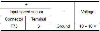
Is the inspection result normal? YES >> GO TO 2.
NO >> GO TO 6.
2.CHECK INPUT SPEED SENSOR GROUND CIRCUIT
Check continuity between input speed sensor harness connector terminal and ground.
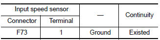
Is the inspection result normal? YES >> GO TO 3.
NO >> Repair or replace malfunctioning parts.
3.CHECK CIRCUIT BETWEEN INPUT SPEED SENSOR AND TCM (PART 1)
- Turn ignition switch OFF.
- Disconnect TCM connector.
- Check continuity between input speed sensor harness connector terminal and TCM harness connector terminal.
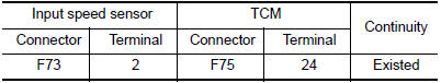
Is the inspection result normal? YES >> GO TO 4.
NO >> Repair or replace malfunctioning parts.
4.CHECK CIRCUIT BETWEEN INPUT SPEED SENSOR AND TCM (PART 2)
Check continuity between input speed sensor harness connector terminal and ground.
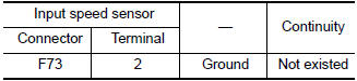
Is the inspection result normal? YES >> GO TO 5.
NO >> Repair or replace malfunctioning parts.
5.CHECK TCM INPUT SIGNALS
- Connect all of disconnected connectors.
- Lift the vehicle.
- Start the engine.
- Check frequency of input speed sensor.
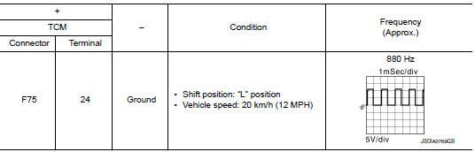
Is the inspection result normal? YES >> INSPECTION END
NO >> Replace input speed sensor. Refer to TM-207, "Removal and Installation".
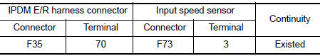
6.CHECK CIRCUIT BETWEEN IPDM E/R AND INPUT SPEED SENSOR
- Turn ignition switch OFF.
- Disconnect IPDM E/R connector.
- Check continuity between IPDM E/R harness connector terminal and input speed sensor harness connector terminals.
Is the check result normal? YES >> GO TO 7.
NO >> Repair or replace malfunctioning parts.
7.DETECT MALFUNCTIONING ITEMS
Check the following items:
- Open circuit or short circuit in harness between ignition switch and IPDM E/R. Refer to PG-15, "Wiring Diagram — Ignition Power Supply —".
- Short circuit in harness between IPDM E/R harness connector terminal 70 and input speed sensor harness connector terminal 3.
- 10A fuse (No.46, located in the IPDM E/R). Refer to PG-68, "IPDM E/R Terminal Arrangement".
- IPDM E/R
Is the check result normal? YES >> INSPECTION END
NO >> Repair or replace malfunctioning parts.
 P0715 input speed sensor A
DTC Description
DTC DETECTION LOGIC
DTC
CONSULT screen terms
(Trouble diagnosis content)
DTC detection condition
P0715
INPUT SPEED SENSOR A
(Input/Turbine Speed Sensor ...
 P0740 torque converter
DTC Description
DTC DETECTION LOGIC
DTC
CONSULT screen terms
(Trouble diagnosis content)
DTC detection condition
P0740
TORQUE CONVERTER
(Torque Converter Clutch Circui ...
Other materials:
Mirrors
Rearview mirror (if so equipped)
Rearview mirror (if so equipped)
Use the night position 1 to reduce glare from
the headlights of vehicles behind you at night.
Use the day position 2 when driving in daylight
hours.
WARNINGUse the night position only when necessary,
because it r ...
Brake pedal
Inspection
BRAKE PEDAL HEIGHT
Check the brake pedal height (H) between the dash lower panel (3) and the
brake pedal upper surface.
CAUTION:
Check the brake pedal height with the floor trim removed.
Brake pedal height (H) from dash lower panel (3)
Refer to BR-54, "Brake Peda ...
Front wiper does not operate
Description
The front wiper does not operate under any operation conditions.
Diagnosis Procedure
Regarding Wiring Diagram information, refer to WW-22, "Wiring Diagram".
1. CHECK WIPER RELAY OPERATION
CONSULT ACTIVE TEST
Select FR WIPER of BCM (WIPER) active test item.
&nb ...
