Nissan Rogue Owners Manual: NISSAN Intelligent Key® battery discharge (if so equipped)
NISSAN Intelligent Key® battery discharge
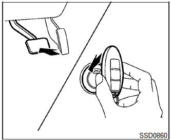
If the battery of the NISSAN Intelligent Key® is discharged, or environmental conditions interfere with the Intelligent Key operation, start the engine according to the following procedure:
- Place the shift lever in the P (Park) position.
- Firmly apply the foot brake.
- Touch the ignition switch with the Intelligent Key as illustrated. (A chime will sound.)
After step 3 is performed, when the ignition switch is pushed without depressing the brake pedal, the ignition switch position will change to ON.
- Push the ignition switch while depressing the brake pedal within ten seconds after the chime sounds. The engine will start.
NOTE:
- When the ignition switch is pushed to the
ON position or the engine is started by the
above procedure, the Intelligent Key battery
discharge indicator appears in the vehicle
information display even when the Intelligent
Key is inside the vehicle. This is not a malfunction.
To turn off the Intelligent Key battery discharge indicator, touch the ignition switch with the Intelligent Key again.
- If the Intelligent Key battery discharge indicator appears, replace the battery as soon as possible. For additional information, refer to “Battery Replacement” in the “Maintenance and do-it-yourself” section of this manual.
 Push-button ignition switch positions
LOCK (Normal parking position):
The ignition switch can only be locked in this
position.
The ignition switch will lock when any door is
opened or closed with the ignition switched off.
ON (Norm ...
 NISSAN vehicle immobilizer system
The NISSAN Vehicle Immobilizer system will not
allow the engine to start without the use of the
registered key.
If the engine fails to start using a registered key
(for example, when interferenc ...
Other materials:
Rear bumper
Exploded View
Rear bumper fascia side bracket
(LH)
Rear mud protector
Rear bumper reinforcement support
(LH)
Rear bumper fascia undercover
(LH)
Rear bumper reinforcement
Rear energy absorber
Rear bumper bracket (LH)
Rear bumper fascia
Rear bumper fascia re ...
P155D generator
DTC Description
DTC DETECTION LOGIC
DTC No.
CONSULT screen terms
(Trouble diagnosis content)
DTC detecting condition
P155D
GENERATOR
(Generator)
ECM receives mechanical malfunction signal sent from generator.
ECM receives electrical malfunction ...
Basic inspection
DIAGNOSIS AND REPAIR WORK FLOW
Work Flow
OVERALL SEQUENCE
DETAILED FLOW
1.GET INFORMATION FOR SYMPTOM
Get detailed information from the customer about the symptom (the
condition and the environment when
the incident/malfunction occurs).
Check operation condition of the ...
