Nissan Rogue Service Manual: P0713 transmission fluid temperature sensor A
DTC Description
DTC DETECTION LOGIC
| DTC | CONSULT screen terms (Trouble diagnosis content) | DTC detection condition |
| P0713 | FLUID TEMP SENSOR A (Transmission Fluid Temperature Sensor A Circuit High) | When all of the following conditions are satisfied and this state is
maintained
for 5 seconds:
|
POSSIBLE CAUSE
- Harness or connector (CVT fluid temperature sensor circuit is open or shorted to power supply)
- CVT fluid temperature sensor
FAIL-SAFE
- Engine coolant temperature when engine start: Temp. ‚Č• 10¬įC (50¬įF)
- Start is slow
- Acceleration is slow
- Engine coolant temperature when engine start: ‚ąí35¬įC (‚ąí31¬įF) ‚ȧ Temp. < 10¬įC (50¬įF)
- Selector shock is large
- Start is slow
- Acceleration is slow
- Engine coolant temperature when engine start: Temp. < ‚ąí35¬įC (‚ąí31¬įF)
- Selector shock is large
- Start is slow
- Acceleration is slow
DTC CONFIRMATION PROCEDURE
1.PREPARATION BEFORE WORK
If another "DTC CONFIRMATION PROCEDURE" occurs just before, turn ignition switch OFF and wait for at least 10 seconds, then perform the next test.
>> GO TO 2.
2.PERFORM DTC CONFIRMATION PROCEDURE
- Start the engine.
- Maintain the following condition for 10 seconds or more.
- Stop the vehicle.
- Check the first trip DTC.
Is ‚ÄúP0713‚ÄĚ detected? YES >> Go to TM-123, "Diagnosis Procedure".
NO-1 >> To check malfunction symptom before repair: Refer to GI-41, "Intermittent Incident".
NO-2 >> Confirmation after repair: INSPECTION END
Diagnosis Procedure
1.CHECK CIRCUIT BETWEEN TCM AND CVT UNIT (PART 1)
- Turn ignition switch OFF.
- Disconnect TCM connector and CVT unit connector.
- Check continuity between TCM harness connector terminals and CVT unit harness connector terminal
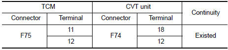
Is the inspection result normal? YES >> GO TO 2.
NO >> Repair or replace malfunctioning parts.
2.CHECK CIRCUIT BETWEEN TCM AND CVT UNIT (PART 2)
- Turn ignition switch ON.
- Check voltage between TCM harness connector terminal and ground.
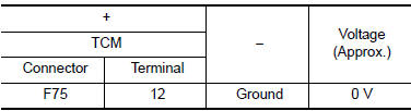
Is the inspection result normal? YES >> GO TO 3.
NO >> Repair or replace malfunctioning parts.
3.CHECK CVT FLUID TEMPERATURE SENSOR
- Turn ignition switch OFF.
- Check resistance between CVT unit connector terminals.
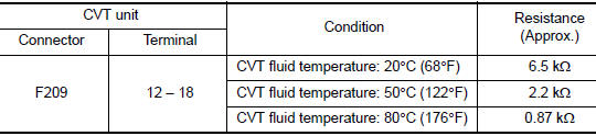
Is the inspection result normal? YES >> INSPECTION END
NO >> There is a malfunction of the CVT fluid temperature sensor. Replace the transaxle assembly.
Refer to TM-220, "Removal and Installation".
 P0712 transmission fluid temperature sensor A
DTC Description
DTC DETECTION LOGIC
DTC
CONSULT screen terms
(Trouble diagnosis content)
DTC detection condition
P0712
FLUID TEMP SENSOR A
(Transmission Fluid Temperat ...
 P0715 input speed sensor A
DTC Description
DTC DETECTION LOGIC
DTC
CONSULT screen terms
(Trouble diagnosis content)
DTC detection condition
P0715
INPUT SPEED SENSOR A
(Input/Turbine Speed Sensor ...
Other materials:
Wiring diagram
REAR WINDOW DEFOGGER SYSTEM
Wiring Diagram
...
Navigation System voice commands
The following voice commands are available for
the Navigation System:
Street Address (address)
Points of Interest (name)
POI by Category
Home
Address Book
Previous Destinations
Enter Address in Steps
Cancel Route
For additional in ...
Ducts and grilles
Exploded View
Side defroster duct (RH)
Defroster nozzle
Side defroster duct (LH)
Center ventilator duct
Heating and cooling unit assembly
Front foot duct (LH)
Front floor connecting duct (LH)
Front floor duct (LH)
Rear center ventilator duct
Adaptor duct 11 ...
