Nissan Rogue Service Manual: Ducts and grilles
Exploded View
- Side defroster duct (RH)
- Defroster nozzle
- Side defroster duct (LH)
- Center ventilator duct
- Heating and cooling unit assembly
- Front foot duct (LH)
- Front floor connecting duct (LH)
- Front floor duct (LH)
- Rear center ventilator duct
- Adaptor duct 11. Front floor duct (RH)
- Front floor connecting duct (RH)
- Front foot duct (RH)
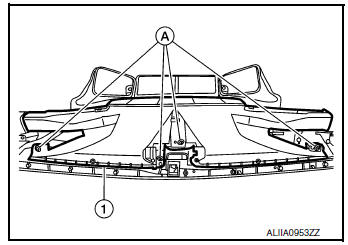
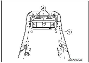
DEFROSTER NOZZLE
DEFROSTER NOZZLE : Removal and Installation
REMOVAL
- Remove side defroster ducts (LH/RH). Refer to VTL-9, "SIDE DEFROSTER DUCT : Removal and Installation".
- Remove screws (A) and defroster nozzle (1).
INSTALLATION
Installation is in the reverse order of removal.
SIDE DEFROSTER DUCT
SIDE DEFROSTER DUCT : Removal and Installation
REMOVAL
- Remove the instrument panel assembly. Refer to IP-14, "INSTRUMENT PANEL ASSEMBLY : Removal and Installation".
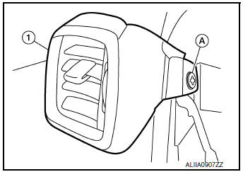
- Remove the screws (A) and the side defroster duct (1).
NOTE: LH side shown; RH similar.
INSTALLATION
Installation is in the reverse order of removal.
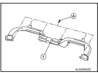
CENTER VENTILATOR DUCT
CENTER VENTILATOR DUCT : Removal and Installation
REMOVAL
- Remove instrument panel assembly. Refer to IP-14, "INSTRUMENT PANEL ASSEMBLY : Removal and Installation".
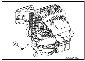
- Remove screws (A) and center ventilator duct (1).
INSTALLATION
Installation is in the reverse order of removal.
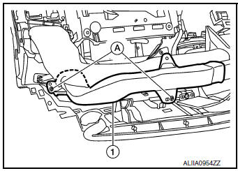
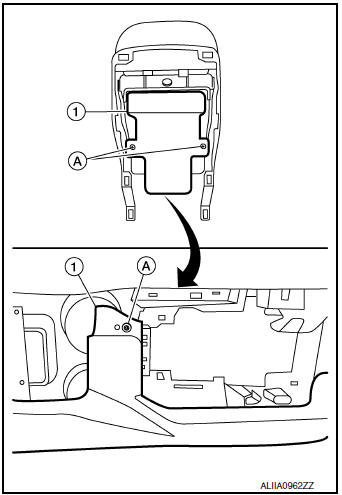
FRONT FOOT DUCT
FRONT FOOT DUCT : Removal and Installation
REMOVAL
Front foot duct (LH)
- Remove instrument lower panel LH. Refer to IP-22, "Removal and Installation"
- Remove front foot duct (LH) screws (A).
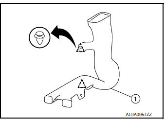
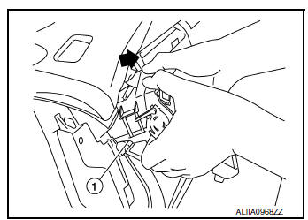
- Release the pawl and remove front foot duct (LH) (1).
 : Pawl
Front foot duct (RH)
- Remove glove box assembly. Refer to IP-23, "Removal and Installation".
- Remove front foot duct (RH) screws (A).
- Release the pawl and remove front foot duct (RH) (1).
 : Pawl
INSTALLATION
Installation is in the reverse order of removal.
FRONT FLOOR DUCT
FRONT FLOOR DUCT : Removal and Installation - Front Floor Connecting Duct
REMOVAL
- Remove the center console side finisher. Refer to IP-18, "Exploded View".
- Release the pawls and remove front floor connecting duct (1).
 : Pawl
NOTE: LH side shown; RH similar.
INSTALLATION
Installation is in the reverse order of removal.
FRONT FLOOR DUCT : Removal and Installation - Front Floor Duct
REMOVAL
- Partially remove front floor trim.
- Remove front floor duct screws.
- Release clips using a suitable tool and remove front foot duct (1).
 : Clip
NOTE: RH side shown; LH similar.
INSTALLATION
Installation is in the reverse order of removal.
ADAPTOR DUCT
ADAPTOR DUCT : Removal and Installation
REMOVAL
- Remove inside key antenna (instrument center). Refer to DLK-271, "INSTRUMENT CENTER : Removal and Installation".
- Remove shift selector finisher. Refer to IP-18, "Exploded View".
- Remove the adaptor duct.
INSTALLATION
Installation is in the reverse order of removal.
REAR CENTER VENTILATOR DUCT
REAR CENTER VENTILATOR DUCT : Removal and Installation
REMOVAL
- Remove center console assembly. Refer to IP-18, "Removal and Installation".
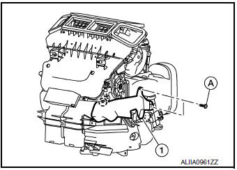
- Remove screws (A) and rear center ventilator duct (1).
INSTALLATION
Installation is in the reverse order of removal.
Exploded View
- Defroster grille
- Side ventilator grille (RH)
- Center ventilator grille
- Side ventilator grille (RH)
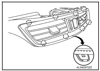
DEFROSTER GRILLE
DEFROSTER GRILLE : Removal and Installation
REMOVAL
- Remove front pillar finishers (LH/RH). Refer to INT-20, "FRONT PILLAR FINISHER : Removal and Installation".
- Release defroster grille clips using a suitable tool.
- Disconnect the harness connectors and remove defroster grille.
INSTALLATION
Installation is in the reverse order of removal.
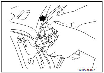
CENTER VENTILATOR GRILLE
CENTER VENTILATOR GRILLE : Removal and Installation
REMOVAL
- Release the pawls using a suitable tool, disconnect the harness connector and remove center ventilator grille assembly from instrument panel.
 : Pawl
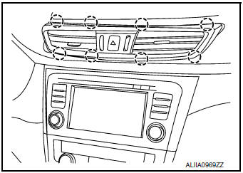
- Disconnect the harness connector (A) from hazard switch (1).
- Release the pawls to remove the center ventilator grilles (LH/ RH).
 : Pawl
INSTALLATION
Installation is in the reverse order of removal.
SIDE VENTILATOR GRILLE
SIDE VENTILATOR GRILLE : Removal and Installation
REMOVAL
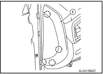
Side ventilator grille (LH)
- Release the pawls using a suitable tool and remove instrument side finisher (LH) (1).
: Pawl
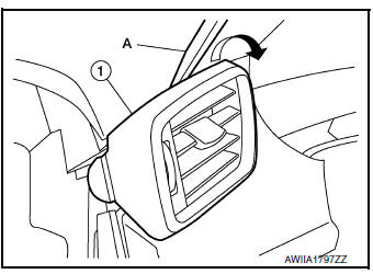
- Insert a suitable tool (A) at the top of the side ventilator grille (1) and release as shown.
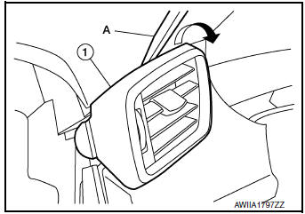
- Remove side ventilator grille (1) in the direction shown (
 ).
).
Side ventilator grille (RH)
- Release the pawls using a suitable tool and remove instrument side finisher (1).
: Pawl
- Remove side ventilator grille (RH) screw (A).
- Insert a suitable tool (A) at the top of the side ventilator grille (1) and release as shown.
- Remove side ventilator grille (1) in the direction shown (
).
INSTALLATION
Installation is in the reverse order of removal.
REAR CENTER VENTILATOR GRILLE
REAR CENTER VENTILATOR GRILLE : Removal and Installation
REMOVAL
- Remove center console rear finisher. Refer to IP-18, "Exploded View".
- Remove screws (A) and rear center ventilator grille (1).
INSTALLATION
Installation is in the reverse order of removal.

 Blower motor
Exploded View
Heating and cooling unit assembly
Blower motor
Screw
Front
Removal and Installation
REMOVAL
Remove glove box assembly. Refer to IP-23, "Removal and ...
Other materials:
P0863 TCM communication
DTC Description
DTC DETECTION LOGIC
DTC
CONSULT screen terms
(Trouble diagnosis content)
DTC detection condition
P0863
CONTROL UNIT (CAN)
(TCM Communication Circuit)
An error is detected at the initial CAN diagnosis of TCM.
POSSIBLE CAUSE
TCM
FAIL-SAFE
...
B0091 front side air bag satellite sensor LH
Description
DTC B0091 FRONT SATELLITE SENSOR LH
The front side air bag satellite sensor LH is wired to the air bag diagnosis
sensor unit. The air bag diagnosis
sensor unit will monitor the front side air bag satellite sensor LH for internal
failures and its circuits for communication
errors. ...
Passenger compartment
CAUTIONNever use a fuse of a higher or lower
amperage rating than specified on the
fuse box cover. This could damage the
electrical system or cause a fire.
If any electrical equipment does not operate,
check for an open fuse.
NOTE:
The fuse box is located on the driver ...
