Nissan Rogue Service Manual: P0712 transmission fluid temperature sensor A
DTC Description
DTC DETECTION LOGIC
| DTC | CONSULT screen terms (Trouble diagnosis content) | DTC detection condition |
| P0712 | FLUID TEMP SENSOR A (Transmission Fluid Temperature Sensor A Circuit Low) | When all of the following conditions are satisfied and this state is
maintained
for 5 seconds:
|
POSSIBLE CAUSE
- Harness or connector (CVT fluid temperature sensor circuit is shorted to ground)
- CVT fluid temperature sensor
FAIL-SAFE
- Engine coolant temperature when engine start: Temp. ‚Č• 10¬įC (50¬įF)
- Start is slow
- Acceleration is slow
- Engine coolant temperature when engine start: ‚ąí35¬įC (‚ąí31¬įF) ‚ȧ Temp. < 10¬įC (50¬įF)
- Selector shock is large
- Start is slow
- Acceleration is slow
- Engine coolant temperature when engine start: Temp. < ‚ąí35¬įC (‚ąí31¬įF)
- Selector shock is large
- Start is slow
- Acceleration is slow
DTC CONFIRMATION PROCEDURE
1.PREPARATION BEFORE WORK
If another "DTC CONFIRMATION PROCEDURE" occurs just before, turn ignition switch OFF and wait for at least 10 seconds, then perform the next test.
>> GO TO 2.
2.PERFORM DTC CONFIRMATION PROCEDURE
- Start the engine and wait for 10 seconds or more.
- Check the first trip DTC.
Is ‚ÄúP0712‚ÄĚ detected? YES >> Go to TM-121, "Diagnosis Procedure".
NO-1 >> To check malfunction symptom before repair: Refer to GI-41, "Intermittent Incident".
NO-2 >> Confirmation after repair: INSPECTION END
Diagnosis Procedure
1.CHECK CIRCUIT BETWEEN TCM AND CVT UNIT
- Turn ignition switch OFF.
- Disconnect TCM connector and CVT unit connector.
- . Check continuity between TCM harness connector terminal and ground.
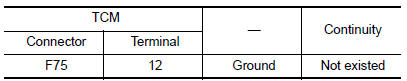
Is the inspection result normal? YES >> GO TO 2.
NO >> Repair or replace malfunctioning part.
2.CHECK CVT UNIT TERMINAL CODE ASSEMBLY
Check continuity between CVT unit connector terminal and ground.
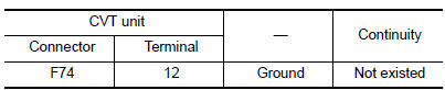
Is the inspection result normal? YES >> GO TO 3.
NO >> There is a malfunction of the CVT unit terminal code assembly. Replace the transaxle assembly.
Refer to TM-220, "Removal and Installation".
3.CHECK CVT FLUID TEMPERATURE SENSOR
Check resistance between CVT unit connector terminals.
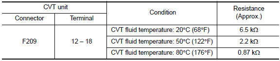
Is the inspection result normal? YES >> INSPECTION END
NO >> There is a malfunction of the CVT fluid temperature sensor. Replace the transaxle assembly.
Refer to TM-220, "Removal and Installation".
 P0711 transmission fluid temperature sensor A
DTC Description
DTC DETECTION LOGIC
DTC
CONSULT screen terms
(Trouble diagnosis content)
DTC detection condition
P0711
FLUID TEMP SENSOR A
(Transmission Fluid Temperat ...
 P0713 transmission fluid temperature sensor A
DTC Description
DTC DETECTION LOGIC
DTC
CONSULT screen terms
(Trouble diagnosis content)
DTC detection condition
P0713
FLUID TEMP SENSOR A
(Transmission Fluid Temperat ...
Other materials:
Child safety
WARNINGDo not allow children to play with the seat
belts. Most seating positions are
equipped with Automatic Locking Retractor
(ALR) mode seat belts. If the seat belt
becomes wrapped around a child’s neck
with the ALR mode activated, the child can
be seriously injured or k ...
Basic inspection
COMPONENT INSPECTION
Inspection
AFTER A COLLISION
WARNING:
Inspect all seat belt assemblies including retractors and attaching hardware
after any collision.
NISSAN/INFINITI recommends that all seat belt assemblies in use during a
collision be replaced
unless the collision was minor and t ...
Speedometer and odometer
Speedometer
The speedometer indicates vehicle speed.
Odometer/Twin trip odometer
The odometer 1 and the twin trip odometer 2
are displayed below the Vehicle Information Display
when the ignition switch is placed in the ON
position.
The odometer records the total distance the vehicle
has ...
