Nissan Rogue Service Manual: P052A, P052B intake valve timing control
DTC Description
DTC DETECTION LOGIC
| DTC No. | CONSULT screen terms (Trouble diagnosis content) | DTC detecting condition |
| P052A | CAMSHAFT POSITION TIMING B1 (Cold start “A” camshaft position timing over-advanced bank 1) | There is a gap between angle of target and phase-control angle degree when the engine is in a cold condition. |
| P052B | CAMSHAFT POSITION TIMING B1 (Cold start “A” camshaft position timing over-retarded bank 1) |
POSSIBLE CAUSE
- Crankshaft position sensor
- Camshaft position sensor
- Intake valve timing control solenoid valve
- Intake valve timing intermediate lock control solenoid valve
- Accumulation of debris to the signal pick-up portion of the camshaft
- Timing chain installation
- Foreign matter caught in the oil groove for intake valve timing control
FAIL-SAFE
Device fix mode
DTC CONFIRMATION PROCEDURE
1.CHECK DTC PRIORITY
If DTC P052A or P052B is displayed with DTC P0075, first perform the trouble diagnosis for DTC P0075.
Is applicable DTC detected? YES >> Perform diagnosis of applicable. Refer to EC-191, "DTC Description".
NO >> GO TO 2.
2.PRECONDITIONING
TESTING CONDITION: Before performing the following procedure, confirm that battery voltage is 10 V or more at idle.
 With CONSULT
- Turn ignition switch OFF and wait at least 10 seconds.
- Turn ignition switch ON.
- Turn ignition switch OFF and wait at least 10 seconds.
- Turn ignition switch ON.
- On the CONSULT screen, select “ENGINE” >> “DATA MONITOR” >> “COOLAN TEMP/S”.
- Check “COOLAN TEMP/S” indication value.
 With GST
Follow the procedure “With CONSULT” above.
Is the value of “COOLAN TEMP/S”−5°C (23°F) and 45°C (113°F)? YES >> GO TO 3.
NO-1 [if it is below − 5°C (23°F)]>>Warm up the engine until the value of “COOLAN TEMP/S” indicates −5°C (23°F) and 45°C (113°F). And then GO TO 3.
NO-2 [if it is above 45°C (113°F)]>>Cool the engine down to the value of “COOLAN TEMP/S” indicates −5°C (23°F) and 45°C (113°F). And then GO TO 3.
3.PERFORM DTC CONFIRMATION PROCEDURE-I
- Turn ignition switch OFF and wait at 10 seconds.
- Turn ignition switch ON.
- Set the selector lever in N range.
- Start the engine and let it idle for 20 seconds or more.
- Check 1st trip DTC.
Is 1st trip DTC detected? YES >> Proceed to EC-365, "Diagnosis Procedure" NO >> INSPECTION END
Diagnosis Procedure
1.CHECK DTC PRIORITY
If DTC P052A or P052B is displayed with DTC P0075, first perform the trouble diagnosis for DTC P0075.
Is applicable DTC detected? YES >> Perform diagnosis of applicable. Refer to EC-191, "DTC Description".
NO >> GO TO 2.
2.INSPECTION START
With CONSULT>>GO TO 3.
Without CONSULT>>GO TO 4.
3.CHECK VTC POSITION
 With CONSULT
- Turn ignition switch ON.
- On the CONSULT screen, select “ENGINE” >> “DATA MONITOR” >> “COOLAN TEMP/S”.
- Check that the “COOLAN TEMP/S” indication value is between −5°C (23°F) and 45°C (113°F).
- Start engine and wait at least 5 seconds.
- On the CONSULT screen, select “ENGINE” >> “DATA MONITOR” >> “INT/V TIM (B1)”.
- Check that the data monitor item indicates as follows:
| Item | Value (°CA) |
| INT/V TIM (B1) | 10 ± 2 |
Is the inspection result normal? YES >> GO TO 12.
NO >> GO TO 4.
4.CHECK OIL PRESSURE WARNING LAMP
- Start engine.
- Check that oil pressure warning lamp is not illuminated.
Is oil pressure warning lamp illuminated? YES >> Refer to LU-7, "Inspection".
NO >> GO TO 5.
5.CHECK INTAKE VALVE TIMING INTERMEDIATE LOCK CONTROL SOLENOID VALVE
Perform Component Inspection of the intake valve timing intermediate lock control solenoid valve. Refer to EC-367, "Component Inspection (Intake Valve Timing Intermediate Lock Control Solenoid Valve)".
Is the inspection result normal? YES >> GO TO 6.
NO >> Repair or replace error-detected parts.
6.CHECK INTAKE VALVE TIMING CONTROL SOLENOID VALVE
Perform Component Inspection of the intake valve timing control solenoid valve. Refer to EC-366, "Component Inspection (Intake Valve Timing Control Solenoid Valve)".
Is the inspection result normal? YES >> GO TO 7.
NO >> Repair or replace error-detected parts.
7.CHECK CRANKSHAFT POSITION SENSOR
Perform Component Inspection of the crankshaft position sensor. Refer to EC-368, "Component Inspection (Crankshaft Position sensor)".
Is the inspection result normal? YES >> GO TO 8.
NO >> Repair or replace error-detected parts.
8.CHECK CAMSHAFT POSITION SENSOR
Perform Component Inspection of the camshaft position sensor. Refer to EC-368, "Component Inspection (Camshaft position sensor)".
Is the inspection result normal? YES >> GO TO 9.
NO >> Repair or replace error-detected parts.
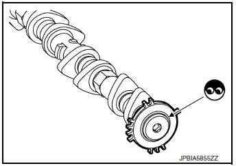
9.CHECK CAMSHAFT (INTAKE)
Check the following.
- Accumulation of debris on the signal plate of camshaft front end
- Chipping signal plate of camshaft front end
Is the inspection result normal? YES >> GO TO 10.
NO >> Remove debris and clean the signal plate of camshaft front end or replace camshaft. Refer to EM-64, "Removal and Installation".
10.CHECK TIMING CHAIN INSTALLATION
Check service records for any recent repairs that may cause timing chain misalignment.
Are there any service records that may cause timing chain misalignment? YES >> Check timing chain installation. Refer to EM-45, "Removal and Installation".
NO >> GO TO 11.
11.CHECK LUBRICATION CIRCUIT
Perform “Inspection of Camshaft Sprocket (INT) Oil Groove”. Refer to EM-72, "Inspection After Installation".
Is the inspection result normal? YES >> GO TO 12.
NO >> Clean lubrication line.
12.CHECK INTERMITTENT INCIDENT
Refer to GI-41, "Intermittent Incident".
>> INSPECTION END
Component Inspection (Intake Valve Timing Control Solenoid Valve)
1.CHECK INTAKE VALVE TIMING CONTROL SOLENOID VALVE-I
- Turn ignition switch OFF.
- Disconnect intake valve timing control solenoid valve harness connector.
- Check resistance between intake valve timing control solenoid valve terminals as per the following
| Terminals | Resistance |
| 1 and 2 | 7.0 - 7.7 Ω [at 20°C (68°F)] |
| 1 or 2 and ground | ∞ Ω (Continuity should not exist) |
Is the inspection result normal? YES >> GO TO 2.
NO >> Replace malfunctioning intake valve timing control solenoid valve. Refer to EM-44, "Exploded View".
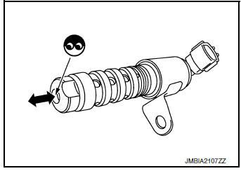
2.CHECK INTAKE VALVE TIMING CONTROL SOLENOID VALVE-II
1. Remove intake valve timing control solenoid valve. Refer to EM-44, "Exploded View".
2. Provide 12 V DC between intake valve timing control solenoid valve terminals 1 and 2, and then interrupt it. Check that the plunger moves as shown in the figure.
CAUTION: Never apply 12 V DC continuously for 5 seconds or more.
Doing so may result in damage to the coil in intake valve timing control solenoid valve.
NOTE: Always replace O-ring when intake valve timing control solenoid valve is removed.
Is the inspection result normal?
YES >> INSPECTION END
NO >> Replace malfunctioning intake valve timing control solenoid valve. Refer to EM-44, "Exploded View".
Component Inspection (Intake Valve Timing Intermediate Lock Control Solenoid Valve)
1.CHECK INTAKE VALVE TIMING INTERMEDIATE LOCK CONTROL SOLENOID VALVE-I
- Turn ignition switch OFF.
- Disconnect intake valve timing intermediate lock control solenoid valve harness connector.
- Check resistance between intake valve timing intermediate lock control solenoid valve terminals as per the following.
| Terminals | Resistance |
| 1 and 2 | 7.0 - 7.7 Ω [at 20°C (68°F)] |
| 1 or 2 and ground | ∞ Ω (Continuity should not exist) |
Is the inspection result normal? YES >> GO TO 2.
NO >> Replace malfunctioning intake valve timing intermediate lock control solenoid valve. Refer to EM- 44, "Exploded View".
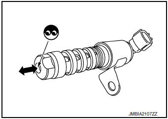
2.CHECK INTAKE VALVE TIMING INTERMEDIATE LOCK CONTROL SOLENOID VALVE-II
- Remove intake valve timing intermediate lock control solenoid valve. Refer to EM-44, "Exploded View".
- Provide 12 V DC between intake valve timing intermediate lock
control solenoid valve terminals 1 and 2, and then interrupt it.
Check that the plunger moves as shown in the figure.
CAUTION: Never apply 12 V DC continuously for 5 seconds or more.
Doing so may result in damage to the coil in intake valve timing intermediate lock control solenoid valve.
NOTE: Always replace O-ring when intake valve timing intermediate lock control solenoid valve is removed.
Is the inspection result normal? YES >> INSPECTION END
NO >> Replace malfunctioning intake valve timing intermediate lock control solenoid valve. Refer to EM- 44, "Exploded View".
Component Inspection (Crankshaft Position sensor)
1.CHECK CRANKSHAFT POSITION SENSOR (POS)-1
- Turn ignition switch OFF.
- Loosen the fixing bolt of the sensor.
- Disconnect crankshaft position sensor (POS) harness connector.
- Remove the sensor.
- Visually check the sensor for chipping.
Is the inspection result normal? YES >> GO TO 2.
NO >> Replace crankshaft position sensor (POS). Refer to EM- 92, "Exploded View".
2.CHECK CRANKSHAFT POSITION SENSOR (POS)-2
Check the resistance between crankshaft position sensor (POS) terminals as per the following.
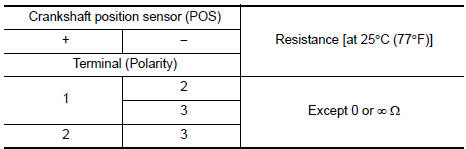
Is the inspection result normal? YES >> INSPECTION END NO >> Replace crankshaft position sensor (POS). Refer to EM-92, "Exploded View".
Component Inspection (Camshaft position sensor)
1.CHECK CAMSHAFT POSITION SENSOR (PHASE)-1
1. Turn ignition switch OFF.
2. Loosen the fixing bolt of the sensor.
3. Disconnect camshaft position sensor (PHASE) harness connector.
4. Remove the sensor.
- Visually check the sensor for chipping.
Is the inspection result normal? YES >> GO TO 2.
NO >> Replace camshaft position sensor (PHASE).
2.CHECK CAMSHAFT POSITION SENSOR (PHASE)-2
Check the resistance camshaft position sensor (PHASE) terminals as per the following.
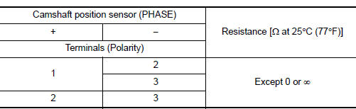
Is the inspection result normal? YES >> INSPECTION END
NO >> Replace camshaft position sensor (PHASE). Refer to EM-64, "Removal and Installation".
 P0524 engine oil pressure
DTC Description
DTC DETECTION LOGIC
DTC No.
CONSULT screen terms
(Trouble diagnosis content)
DTC detecting condition
P0524
ENGINE OIL PRESSURE
(Engine oil pressure too ...
 P0603, P062F ECM
DTC Description
DTC DETECTION LOGIC
DTC No.
CONSULT screen terms
(Trouble diagnosis content)
DTC detecting condition
P0603
ECM BACK UP/CIRCUIT
[Internal Control Module ...
Other materials:
Front wiper motor
Removal and Installation
REMOVAL
Remove the front drive assembly. Refer to WW-66, "Removal and
Installation".
Remove the bolts (A) from the front wiper drive assembly (1)
and the front wiper motor (2).
Separate the wiper motor (1) from the front wiper drive ...
Normal operating condition
Description
FUEL CUT CONTROL (AT NO LOAD AND HIGH ENGINE SPEED)
If the engine speed is above 1,800 rpm under no load (for example, the
selector lever position is neutral and
engine speed is over 1,800 rpm) fuel will be cut off after some time. The exact
time when the fuel is cut off varies
b ...
Unit disassembly and assembly
FRONT COMBINATION LAMP
Exploded View
Front combination lamp
Turn signal lamp bulb socket
Disassembly and Assembly
DISASSEMBLY
Remove front combination lamp. Refer to EXL-268, "Removal and
Installation".
Rotate the turn signal lamp bulb socket counterclo ...
