Nissan Rogue Service Manual: P0222, P0223 TP sensor
DTC Description
DTC DETECTION LOGIC
| DTC No. | CONSULT screen terms (Trouble diagnosis content) | DTC detecting condition |
| P0222 | TP SEN 1/CIRC-B1 (Throttle/pedal position sensor/switch ″B″ circuit low) | An excessively low voltage from the TP sensor 1 is sent to ECM. |
| P0223 | TP SEN 1/CIRC-B1 (Throttle/pedal position sensor/switch ″B″ circuit high) | An excessively high voltage from the TP sensor 1 is sent to ECM. |
POSSIBLE CAUSE
- Harness or connectors (TP sensor 1 circuit is open or shorted.)
- Electric throttle control actuator (TP sensor 1)
FAIL-SAFE
- The ECM controls the electric throttle control actuator in regulating the throttle opening in order for the idle position to be within +10 degrees.
- The ECM regulates the opening speed of the throttle valve to be slower than the normal condition. So, the acceleration will be poor.
DTC CONFIRMATION PROCEDURE
1.CHECK DTC PRIORITY
If DTC P0222 or P0223 is displayed with DTC P0643, first perform the trouble diagnosis for DTC P0643.
Is applicable DTC detected? YES >> Perform diagnosis of applicable. Refer to EC-379, "DTC Description".
NO >> GO TO 2.
2.PRECONDITIONING
If DTC Confirmation Procedure has been previously conducted, always perform the following procedure before conducting the next test.
- Turn ignition switch OFF and wait at least 10 seconds.
- Turn ignition switch ON.
- Turn ignition switch OFF and wait at least 10 seconds.
TESTING CONDITION: Before performing the following procedure, confirm that battery voltage is more than 8 V at idle.
>> GO TO 3.
3.PERFORM DTC CONFIRMATION PROCEDURE
- Start engine and let it idle for 1 second.
- Check DTC.
Is DTC detected? YES >> Proceed to EC-284, "Diagnosis Procedure".
NO >> INSPECTION END
Diagnosis Procedure
1.CHECK DTC PRIORITY
If DTC P0222 or P0223 is displayed with DTC P0643, first perform the trouble diagnosis for DTC P0643.
Is applicable DTC detected? YES >> Perform diagnosis of applicable. Refer to EC-379, "DTC Description".
NO >> GO TO 2.
2.CHECK THROTTLE POSITION SENSOR 1 POWER SUPPLY
- Turn ignition switch OFF.
- Disconnect electric throttle control actuator harness connector.
- Turn ignition switch ON.
- Check the voltage between electric throttle control actuator harness connector and ground.
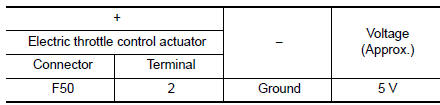
Is the inspection result normal? YES >> GO TO 4.
NO >> GO TO 3.
3.CHECK THROTTLE POSITION SENSOR 1 POWER SUPPLY CIRCUIT
- Turn ignition switch OFF.
- Disconnect ECM harness connector.
- Check the continuity between electric throttle control actuator harness connector and ECM harness connector.
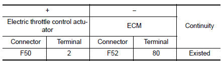
- Also check harness for short to ground.
Is the inspection result normal? YES >> Perform the trouble diagnosis for power supply circuit.
NO >> Repair or replace error-detected parts.
4.CHECK THROTTLE POSITION SENSOR 1 GROUND CIRCUIT
- Turn ignition switch OFF.
- Disconnect ECM harness connector.
- Check the continuity between electric throttle control actuator harness connector and ECM harness connector.
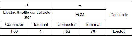
- Also check harness for short to power.
Is the inspection result normal? YES >> GO TO 5.
NO >> Repair or replace error-detected parts.
5.CHECK THROTTLE POSITION SENSOR 1 INPUT SIGNAL CIRCUIT
- Check the continuity between electric throttle control actuator harness connector and ECM harness connector.
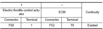
- Also check harness for short to ground and to power.
Is the inspection result normal? YES >> GO TO 6.
NO >> Repair open circuit or short to ground or short to power in harness or connectors.
6.CHECK THROTTLE POSITION SENSOR
Check the throttle position sensor. Refer to EC-286, "Component Inspection".
Is the inspection result normal? YES >> GO TO 7.
NO >> Replace electric throttle control actuator. Refer to EM-26, "Removal and Installation".
7.CHECK INTERMITTENT INCIDENT
Refer to GI-41, "Intermittent Incident".
>> INSPECTION END
Component Inspection
1.CHECK THROTTLE POSITION SENSOR
- Turn ignition switch OFF.
- Reconnect all harness connectors disconnected.
- Perform “ Throttle Valve Closed Position Learning”. Refer to EC-140, "Work Procedure".
- Turn ignition switch ON.
- Set selector lever to D position.
- Check the voltage between ECM harness connector terminals as per the following conditions.
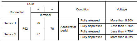
Is the inspection result normal? YES >> INSPECTION END
NO >> Replace electric throttle control actuator. Refer to EM-26, "Removal and Installation".
 P0197, P0198 EOT sensor
DTC Description
DTC DETECTION LOGIC
DTC No.
CONSULT screen terms
(Trouble diagnosis content)
DTC detecting condition
P0197
EOT SEN/CIRC
(Engine oil temperature sensor ...
 P0300, P0301, P0302, P0303, P0304 misfire
DTC Description
DTC DETECTION LOGIC
When a misfire occurs, engine speed will fluctuate. If the engine speed
fluctuates enough to cause the crankshaft
position (CKP) sensor (POS) signal to vary, E ...
Other materials:
U110f lost communication (ECM)
DTC Description
DTC DETECTION LOGIC
DTC
CONSULT screen terms
(Trouble diagnosis content)
DTC detection condition
U110F
LOST COMM (ECM)
(Lost Communication With ECM)
When the ignition switch is ON, TCM is unable to receive the CAN
communications
signal from ...
Front wiper auto stop signal circuit
Component Function Check
1. CHECK FRONT WIPER (AUTO STOP) SIGNAL
Select FR WIPER STOP of BCM (WIPER) data monitor item.
Operate the front wiper.
Check that FR WIPER STOP changes from ON to OFF according to the
wiper position
Is the inspection result normal?
YES ...
Normal operating condition
Description
FRONT WIPER PROTECTION FUNCTION
IPDM E/R detects front wiper stop position by a front wiper stop position
signal.
When a front wiper stop position signal is in the conditions listed below, IPDM
E/R stops power supply to wiper
after repeating a front wiper 10 seconds activation ...
