Nissan Rogue Service Manual: Front wiper auto stop signal circuit
Component Function Check
1. CHECK FRONT WIPER (AUTO STOP) SIGNAL
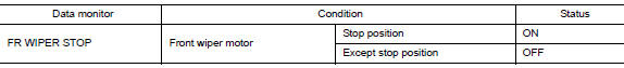
- Select FR WIPER STOP of BCM (WIPER) data monitor item.
- Operate the front wiper.
- Check that FR WIPER STOP changes from ON to OFF according to the wiper position
Is the inspection result normal? YES >> Front wiper auto stop signal circuit is normal.
NO >> Refer to WW-40, "Diagnosis Procedure".
Diagnosis Procedure
Regarding Wiring Diagram information, refer to WW-22, "Wiring Diagram".
1. CHECK FRONT WIPER MOTOR (AUTO STOP) OUTPUT VOLTAGE
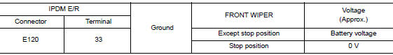
- Turn the ignition switch ON.
- Check voltage between IPDM E/R harness connector and ground.
Is the inspection result normal? YES >> Check for intermittent failure.
NO >> GO TO 2.
2. CHECK FRONT WIPER MOTOR (AUTO STOP) SHORT CIRCUIT
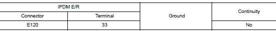
- Turn the ignition switch OFF.
- Disconnect IPDM E/R and front wiper motor.
- Check continuity between IPDM E/R harness connector and ground.
Is the inspection result normal? YES >> Repair or replace harness.
NO >> GO TO 3.
3. CHECK FRONT WIPER MOTOR (AUTO STOP) CIRCUIT CONTINUITY
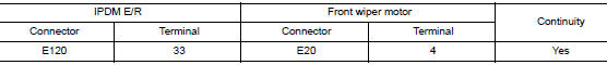
Check continuity between IPDM E/R harness connector and front wiper motor harness connector.
Is the inspection result normal?
YES >> Replace front wiper motor. Refer to WW-67, "Removal and Installation".
NO >> Repair or replace harness.
 Front wiper motor HI circuit
Component Function Check
1.CHECK FRONT WIPER HI OPERATION
CONSULT ACTIVE TEST
Select FR WIPER of BCM (WIPER) active test item.
Check front wiper operation.
HI : Front wiper (HI ...
 Front wiper motor ground circuit
Diagnosis Procedure
Regarding Wiring Diagram information, refer to WW-22, "Wiring Diagram".
1. CHECK FRONT WIPER MOTOR GROUND CIRCUIT
Turn the ignition switch OFF.
Discon ...
Other materials:
ECU diagnosis information
A/C AUTO AMP.
Reference Value
VALUES ON THE DIAGNOSIS TOOL
TERMINAL LAYOUT
PHYSICAL VALUES
DTC Inspection Priority Chart
If some DTCs are displayed at the same time, perform inspections one by one
based on the following priority
chart.
Priority
Det ...
Wiring diagram
HEADLAMP
Wiring Diagram
DAYTIME LIGHT SYSTEM
Wiring Diagram
AUTO LIGHT SYSTEM
Wiring Diagram
FRONT FOG LAMP SYSTEM
Wiring Diagram
TURN SIGNAL AND HAZARD WARNING LAMP SYSTEM
Wiring Diagr ...
Unit removal and installationEMBER
REAR SUSPENSION M
Exploded View
Rear suspension member
Suspension member stay
(RH)
Suspension member stay (LH)
Bound bumper
Front
Removal and Installation - FWD
REMOVAL
Remove wheel and tires using power tool. Refer to WT-60, "Exploded
Vie ...
