Nissan Rogue Service Manual: ECU diagnosis information
A/C AUTO AMP.
Reference Value
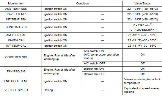
VALUES ON THE DIAGNOSIS TOOL
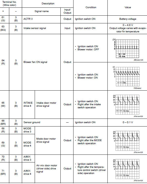
TERMINAL LAYOUT

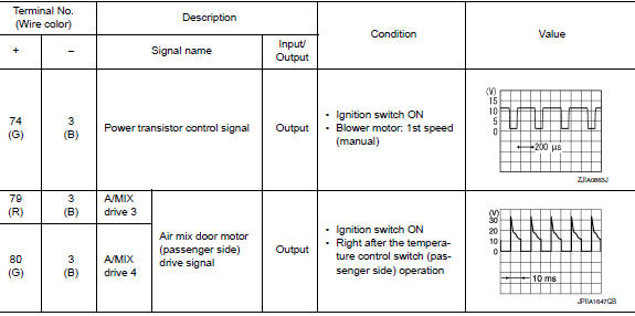
PHYSICAL VALUES


DTC Inspection Priority Chart
If some DTCs are displayed at the same time, perform inspections one by one based on the following priority chart.
|
Priority |
Detected items (DTC) |
| 1 |
|
| 2 |
|
DTC Index
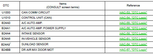
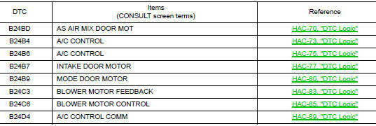
*: Perform self-diagnosis under direct sunlight. When performing indoors, aim a light (more than 60 W) at sunload sensor, otherwise selfdiagnosis reports an error even though the sunload sensor is functioning normally.
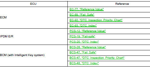
ECM, IPDM E/R, BCM
List of ECU Reference
 System description
Component Part Location
RH side of engine compartment
RH front of vehicle (view with front
bumper fascia removed)
LH front of vehicle (view with front
bumper fascia remove ...
 Wiring diagram
AUTOMATIC AIR CONDITIONING SYSTEM
Wiring Diagram
...
Other materials:
NISSAN Intelligent Key® Operation
NISSAN Intelligent Key® Operation
You can lock or unlock the doors without taking
the Intelligent Key out of your pocket or bag.
When you carry the Intelligent Key with you, you
can lock or unlock all doors by pushing the door
handle request switch within the range of operation.
Loc ...
Removal and installation
FRONT COMBINATION LAMP
Exploded View
Front fender
Front combination lamp
Clip
Removal and Installation
REMOVAL
Remove front bumper fascia. Refer to EXT-17, "Removal and
Installation".
Remove front combination lamp bolts and clip.
Pull front combinat ...
Steering wheel
Inspection
STEERING WHEEL AXIAL END PLAY
Check installation conditions of steering gear, front suspension
assembly, axle and steering column.
Check if movement exists when steering wheel is moved up and down,
to the left and right and to the axial
direction.
Steering wh ...
