Nissan Rogue Service Manual: Wiring diagram
AUTOMATIC AIR CONDITIONING SYSTEM
Wiring Diagram

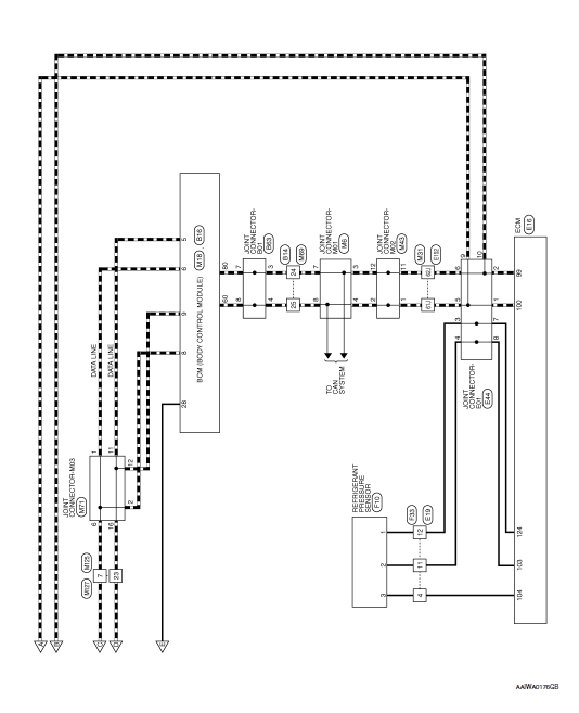
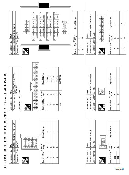

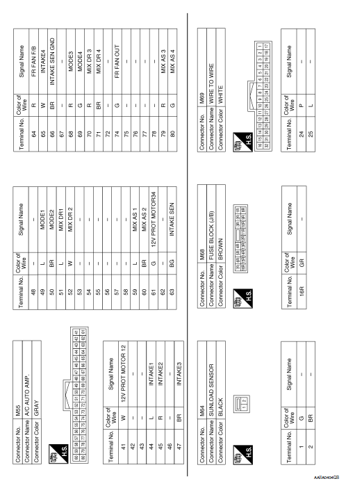

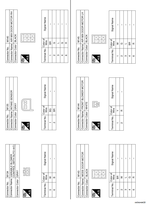
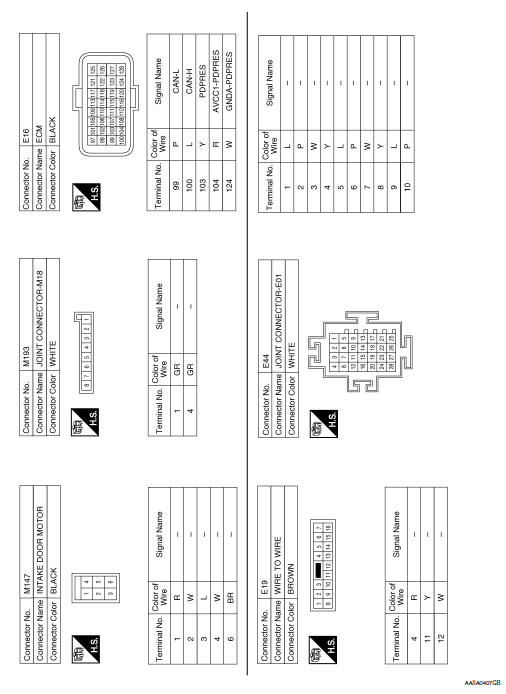

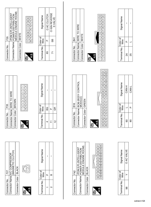

 ECU diagnosis information
A/C AUTO AMP.
Reference Value
VALUES ON THE DIAGNOSIS TOOL
TERMINAL LAYOUT
PHYSICAL VALUES
DTC Inspection Priority Chart
If some DTCs are displayed at the same time, perf ...
 Basic inspection
DIAGNOSIS AND REPAIR WORKFLOW
Work Flow
OVERALL SEQUENCE
DETAILED FLOW
1.INTERVIEW CUSTOMER
Interview the customer to obtain as much information as possible about the
conditions and environ ...
Other materials:
Diagnosis system [ABS actuator and electric unit (control
unit)]
CONSULT Function
APPLICATION ITEMS
CONSULT can display each diagnostic item using the diagnostic test modes as
follows.
Mode
Function description
ECU identification
Parts number of ABS actuator and electric unit (control unit) can be
read.
Self Diagnos ...
Exhaust manifold and three way
catalyst
Exploded View
Cylinder head
Exhaust manifold and three way
catalyst gasket
Exhaust manifold cover (upper)
Exhaust manifold and three way catalyst
Exhaust manifold cover (lower
front)
Exhaust manifold cover (lower rear)
Air fuel ratio (A/F) senso ...
Precaution
Precaution for Supplemental Restraint System (SRS) "AIR BAG" and "SEAT
BELT
PRE-TENSIONER"
The Supplemental Restraint System such as ÔÇťAIR BAGÔÇŁ and ÔÇťSEAT BELT PRE-TENSIONERÔÇŁ,
used along
with a front seat belt, helps to reduce the risk or severity of injury to the
...
