Nissan Rogue Service Manual: Unit removal and installationEMBER
REAR SUSPENSION M
Exploded View
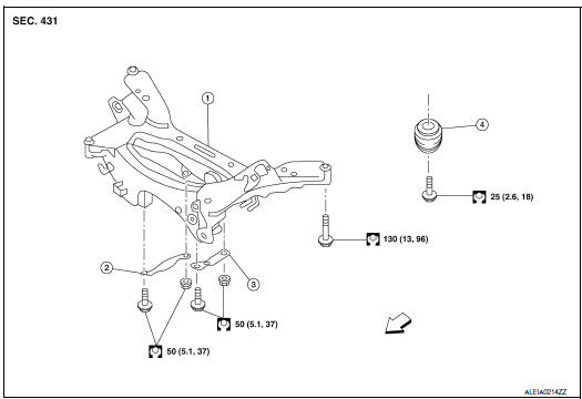
- Rear suspension member
- Suspension member stay (RH)
- Suspension member stay (LH)
- Bound bumper
 Front
Front
Removal and Installation - FWD
REMOVAL
- Remove wheel and tires using power tool. Refer to WT-60, "Exploded View".
- Remove muffler assembly. Refer to EX-5, "Exploded View".
- Remove coil spring. Refer to RSU-8, "Removal and Installation - FWD".
- Remove lower link. Refer to RSU-17, "Removal and Installation".
- Remove upper link. Refer to BR-43, "BRAKE CALIPER ASSEMBLY : Removal and Installation".
- Remove rear stabilizer bar.Refer to RSU-21, "Removal and Installation".
- Remove rear shock absorber. Refer to RSU-14, "Removal and Installation".
- Set suitable jack under rear suspension member.
- Remove bolts from rear suspension member.
- Slowly lower suitable jack and remove rear suspension member.
CAUTION: Secure suspension assembly to a suitable jack while removing it.
INSTALLATION Installation is in the reverse order of the removal.
- When installing suspension member stay, face each arrow on the part toward the inside of the vehicle.
- Align the matching marks made during removal when reusing the disc brake rotor.
- Perform the final tightening of each parts removed when removing rear suspension assembly under unladen conditions.
- Check wheel sensor harness for proper connection. Refer to BRC-133, "REAR WHEEL SENSOR : Exploded View".
Removal and Installation - AWD
REMOVAL
- Remove wheel and tires using power tool. Refer to WT-60, "Exploded View".
- Remove muffler assembly. Refer to EX-5, "Exploded View".
- Remove coil spring. Refer to RSU-10, "Removal and Installation - AWD".
- Remove lower link. Refer to RSU-17, "Removal and Installation".
- Remove upper link. Refer to BR-43, "BRAKE CALIPER ASSEMBLY : Removal and Installation".
- Remove rear stabilizer bar.Refer to RSU-21, "Removal and Installation".
- Remove rear drive shaft. Refer to RAX-19, "Removal and Installation".
- Remove rear propeller shaft. Refer to DLN-99, "Removal and Installation".
- Remove rear final drive. Refer to DLN-119, "Removal and Installation".
- Remove rear shock absorber. Refer to RSU-14, "Removal and Installation".
- Set suitable jack under rear suspension member.
- Remove bolts from rear suspension member.
- Slowly lower suitable jack and remove rear suspension member.
CAUTION: Secure suspension assembly to a suitable jack while removing it.
- Perform the inspection after removal. Refer to RSU-23, "Inspection".
INSTALLATION
Installation is in the reverse order of the removal.
- When installing suspension member stay, face each arrow on the part toward the inside of the vehicle.
- Align the matching marks made during removal when reusing the disc brake rotor.
- Perform the final tightening of each parts removed when removing rear suspension assembly under unladen conditions.
- Check wheel sensor harness for proper connection. Refer to BRC-133, "REAR WHEEL SENSOR : Exploded View".
- Perform the inspection after installation. Refer to RSU-20,
"Inspection".
Inspection
INSPECTION AFTER REMOVAL
Check rear suspension member for deformation, cracks, or any other damage. Replace it if necessary.
INSPECTION AFTER INSTALLATION
- Adjust parking brake operation. Refer to PB-4, "Inspection and Adjustment".
- Check wheel alignment. Refer to RSU-6, "Inspection".
 Rear stabilizer
Exploded View
Rear stabilizer bar
Connecting rod (RH)
Rear stabilizer bar bushing
Rear stabilizer bar clamp
Connecting rod (LH)
Front
Removal and ...
 Service data and specifications (SDS)
Wheel Alignment (Unladen*1)
*1: Fuel, engine coolant, and lubricants are full. Spare tire, jack, hand
tools, and mats are in designated positions.
*2: Since an adjustment mechanism is not incl ...
Other materials:
Operating tips
When the engine coolant temperature and
outside air temperature are low, the air flow
from the foot outlets may not operate for a
maximum of 150 seconds. However, this is
not a malfunction. After the coolant temperature
warms up, air flow from the foot outlets
will operate normally.
...
Vehicle information
Identification information
Model Variation
FWD Model
AWD Model
Prefix and Suffix Designations
Identification Number
Air conditioner specification label
Emission control information label
Vehicle identification number chassis
number (center of bulkhead) ...
Passenger compartment
CAUTIONNever use a fuse of a higher or lower
amperage rating than specified on the
fuse box cover. This could damage the
electrical system or cause a fire.
If any electrical equipment does not operate,
check for an open fuse.
NOTE:
The fuse box is located on the driver ...
