Nissan Rogue Service Manual: P0181 FTT sensor
DTC Description
DTC DETECTION LOGIC
| DTC No. | CONSULT screen terms (Trouble diagnosis content) | DTC detecting condition | |
| P0181 | FTT SENSOR (Fuel temperature sensor ″A″ circuit range/ performance) | A | Rationally incorrect voltage from the sensor is sent to ECM, compared with the voltage signals from ECT sensor and intake air temperature sensor. |
| B | The comparison result of signals transmitted to ECM from each temperature sensor (IAT sensor, ECT sensor, EOT sensor, and FTT sensor) shows that the voltage signal of the FTT sensor is higher/lower than that of other temperature sensors when the engine is started with its cold state. | ||
POSSIBLE CAUSE
DTC P0181 - A
- Harness or connectors (FTT sensor circuit is open or shorted.)
- FTT sensor
- Combination meter
DTC P0181 - B
- Harness or connectors (High or low resistance in the FTT sensor circuit)
- FTT sensor
FAIL-SAFE
Not applicable
DTC CONFIRMATION PROCEDURE
1.INSPECTION START
Is it necessary to erase permanent DTC? YES >> GO TO 7.
NO >> GO TO 2.
2.PRECONDITIONING
If DTC CONFIRMATION PROCEDURE has been previously conducted, always perform the following procedure before conducting the next test.
- Turn ignition switch OFF and wait at least 10 seconds.
- Turn ignition switch ON.
- Turn ignition switch OFF and wait at least 10 seconds.
>> GO TO 3.
3.PERFORM DTC CONFIRMATION PROCEDURE FOR MALFUNCTION A-1
- Turn ignition switch ON and wait at least 10 seconds.
- Check 1st trip DTC.
Is 1st trip DTC detected? YES >> Proceed to EC-272, "Diagnosis Procedure".
NO >> GO TO 4.
4.CHECK ENGINE COOLANT TEMPERATURE
 With CONSULT
- Select ŌĆ£COOLAN TEMP/SŌĆØ in ŌĆ£DATA MONITORŌĆØ of ŌĆ£ENGINEŌĆØ using CONSULT.
- Check ŌĆ£COOLAN TEMP/SŌĆØ value.
 With GST
Follow the procedure ŌĆ£With CONSULTŌĆØ above.
ŌĆ£COOLAN TEMP/SŌĆØ less than 60┬░C (140┬░F)? YES >> INSPECTION END
NO >> GO TO 5.
5.PERFORM DTC CONFIRMATION PROCEDURE FOR MALFUNCTION A-2
 With CONSULT
- Cool engine down until ŌĆ£COOLAN TEMP/SŌĆØ is less than 60┬░C (140┬░F).
- Wait at least 10 seconds.
- Check 1st trip DTC.
 With GST
Follow the procedure ŌĆ£With CONSULTŌĆØ above.
Is 1st trip DTC detected? YES >> Proceed to EC-272, "Diagnosis Procedure".
NO >> GO TO 6.
6.CHECK FUEL TANK TEMPERATURE (FTT) SENSOR
- Turn ignition switch OFF.
- Disconnect fuel level sensor unit and fuel pump harness connector.
- Remove fuel level sensor unit. Refer to FL-6, "Removal and Installation".
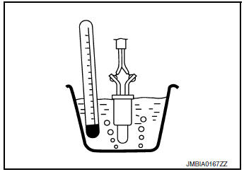
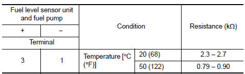
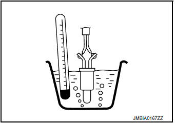
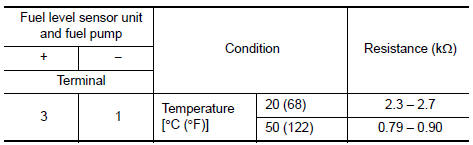
- Check resistance between fuel level sensor unit and fuel pump terminals by heating with hot water as shown in the figure.
Is the inspection result normal? YES >> GO TO 9.
NO >> Proceed to EC-272, "Diagnosis Procedure".
7.PRECONDITIONING
If DTC CONFIRMATION PROCEDURE has been previously conducted, always perform the following procedure before conducting the next test.
- Turn ignition switch OFF and wait at least 10 seconds.
- Turn ignition switch ON.
- Turn ignition switch OFF and wait at least 10 seconds.
TESTING CONDITION:
- Before performing the following procedure, do not add fuel.
- Before performing the following procedure, check that fuel level is between 1/4 and 4/4.
- Before performing the following procedure, confirm that battery voltage is 11 V or more at idle.
>> GO TO 8.
8.PERFORM DTC CONFIRMATION PROCEDURE B
- Move the vehicle to a cool place.
NOTE: Cool the vehicle in an environment of ambient air temperature between −10┬░C (14┬░F) and 35┬░C (95┬░F).
- Turn ignition switch OFF and leave the vehicle for 12 hours.
CAUTION: Never turn ignition switch ON during this procedure.
NOTE: The vehicle must be cooled with the food open.
- Start engine and let it idle for 5 minutes or more.
CAUTION:Never turn ignition switch off during idling.
- Check 1st trip dtc.
Is 1st trip DTC detected? YES >> Proceed to EC-272, "Diagnosis Procedure".
NO >> INSPECTION END
9.CHECK INTERMITTENT INCIDENT
Refer to GI-41, "Intermittent Incident".
>> INSPECTION END
Diagnosis Procedure
1.INSPECTION START
Confirm the detected malfunction (A or B). Refer to EC-270, "DTC Description".
Which malfunction is detected? A >>GO TO 2.
B >>GO TO 6.
2.CHECK DTC WITH COMBINATION METER
Check DTC with combination meter. Refer to MWI-21, "CONSULT Function (METER/M&A)".
Is the inspection result normal? YES >> GO TO 3.
NO >> Proceed to MWI-62, "Component Function Check".
3.CHECK FUEL TANK TEMPERATURE (FTT) SENSOR POWER
- Turn ignition switch OFF.
- Disconnect fuel level sensor unit and fuel pump harness connector.
- Turn ignition switch ON.
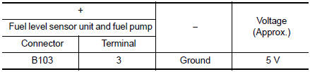
- Check the voltage between fuel level sensor unit and fuel pump harness connector and ground.
Is the inspection result normal? YES >> GO TO 5.
NO >> GO TO 4.
4.CHECK FUEL TANK TEMPERATURE (FTT) SENSOR POWER SUPPLY CIRCUIT
- Turn ignition switch OFF.
- Disconnect ECM harness connector.
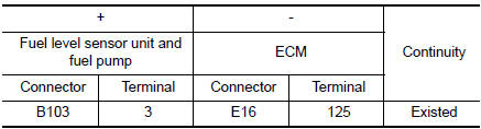
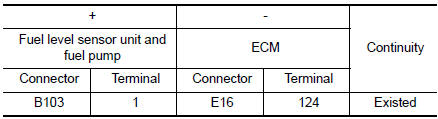
- Check the continuity between fuel level sensor unit and fuel pump harness connector and ECM harness connector.
- Also check harness for short to ground and to power.
Is the inspection result normal? YES >> Perform the trouble diagnosis for power supply circuit.
NO >> Repair or replace error-detected parts.
5.CHECK FTT SENSOR GROUND CIRCUIT
- Turn ignition switch OFF.
- Disconnect ECM harness connector.
- Check the continuity between fuel level sensor unit and fuel pump harness connector and ECM harness connector.
- Also check harness for short to power.
Is the inspection result normal? YES >> GO TO 6.
NO >> Repair or replace error-detected parts.
6.CHECK FUEL TANK TEMPERATURE (FTT) SENSOR
Check the FTT sensor. Refer to EC-273, "Component Inspection".
Is the inspection result normal? YES >> Check intermittent incident. Refer to GI-41, "Intermittent Incident".
NO >> Replace fuel level sensor unit and fuel pump. Refer to FL-6, "Removal and Installation".
Component Inspection
1.CHECK FUEL TANK TEMPERATURE (FTT) SENSOR
- Turn ignition switch OFF.
- Disconnect fuel level sensor unit and fuel pump harness connector.
- Remove fuel level sensor unit. Refer to FL-6, "Removal and Installation".
- Check resistance between fuel level sensor unit and fuel pump terminals by heating with hot water as shown in the figure.
the inspection result normal? YES >> INSPECTION END
NO >> Replace fuel level sensor unit and fuel pump. Refer to FL-6, "Removal and Installation".
 P0172 fuel injection system function
DTC Description
DTC DETECTION LOGIC
With the Air/Fuel Mixture Ratio Self-Learning Control, the actual mixture
ratio can be brought closely to the
theoretical mixture ratio based on the mixture ra ...
 P0182, P0183 FTT sensor
DTC Description
DTC DETECTION LOGIC
DTC No.
CONSULT screen terms
(Trouble diagnosis content)
DTC detecting condition
P0182
FTT SEN/CIRCUIT
(Fuel temperature sensor ...
Other materials:
Basic inspection
DIAGNOSIS AND REPAIR WORK FLOW
Work Flow
DETAILED FLOW
1.INTERVIEW FROM THE CUSTOMER
Clarify customer complaints before inspection. First of all, perform an
interview utilizing DAS-202, "Diagnostic
Work Sheet" and reproduce the symptom as well as fully understand it. Ask
customer ...
Precaution
Precaution for Supplemental Restraint System (SRS) "AIR BAG" and "SEAT
BELT
PRE-TENSIONER"
The Supplemental Restraint System such as ŌĆ£AIR BAGŌĆØ and ŌĆ£SEAT BELT PRE-TENSIONERŌĆØ,
used along
with a front seat belt, helps to reduce the risk or severity of injury to the
...
Child safety
WARNINGDo not allow children to play with the seat
belts. Most seating positions are
equipped with Automatic Locking Retractor
(ALR) mode seat belts. If the seat belt
becomes wrapped around a childŌĆÖs neck
with the ALR mode activated, the child can
be seriously injured or k ...
