Nissan Rogue Service Manual: Oil cooler
Exploded View
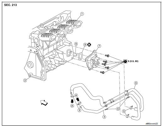
- Intake manifold
- Cylinder block
- Clamp
- Water hose
- Water hose clip
- Water hose
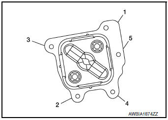
- Oil cooler
- Gasket
- Oil cooler relief valve
 Front
Front
Removal and Installation
WARNING: Be careful not to burn yourself, as engine oil and engine coolant may be hot.
NOTE: When removing components such as hoses, tubes/lines, etc., cap or plug openings to prevent fluid from spilling.
REMOVAL
- Drain engine coolant. Refer to CO-8, "Draining".
- Remove front air spoiler (RH). Refer to EXT-16, "Exploded View"
- Remove fender protector (RH). Refer to EXT-28, "FENDER PROTECTOR : Exploded View".
- Disconnect water hoses from the oil cooler.
- Remove oil cooler bolts in reverse numerical order.
- Remove oil cooler.
CAUTION:
- Be careful not to get burned when engine and engine oil may be hot.
- When removing, prepare a shop cloth to absorb any engine oil leaks or spillage.
- Completely wipe off any engine oil that adheres to engine and vehicle.
- Remove relief valve and O-ring, (if necessary).
INSTALLATION
Installation is in the reverse order of removal.
- Tighten oil cooler to specification as shown.
CAUTION:
- Do not reuse O-ring.
- Ensure O-ring and oil cooler sealing surface is free from dust, flaws, or deformation.
- Ensure water hose assembly is installed without kinks or areas of collapse.
- Replace relief valve, if removed.
Inspection
INSPECTION AFTER REMOVAL
Oil Cooler
Check oil cooler for cracks. Check oil cooler for clogging by blowing through engine coolant inlet. If necessary, replace oil cooler.
Relief valve
Inspect relief valve for movement, cracks, and breaks by pushing the ball. If replacement is necessary, remove the valve by prying it out using a suitable tool. Install a new valve by tapping it in place.
INSPECTION AFTER INSTALLATION
- Check the engine oil level and the engine coolant level and add engine oil and engine coolant. Refer to LU-7, "Inspection" and CO-8, "Inspection".
- Start the engine, and check that there are no leaks of engine oil or engine coolant.
- Stop the engine and wait for 5 minutes.
- Check the engine oil level and the engine coolant level again. Refer to LU-7, "Inspection" and CO-8, "Inspection".

 Oil pump
Exploded View
Front cover (Oil pump body united)
Outer rotor
Inner rotor
Oil pump cover
Regulator valve
Regulator valve spring
Regulator valve plug
CAUTION ...
Other materials:
NISSAN Intelligent Key® (if so equipped)
Replace the battery in the Intelligent Key as follows:
Remove the mechanical key from the Intelligent
Key.
Insert a small screwdriver A into the slit B
of the corner and twist it to separate the
upper part from the lower part. Use a cloth to
protect the casing.
Replace th ...
U0141 lost communication (BCM A)
DTC Description
DTC DETECTION LOGIC
DTC
CONSULT screen terms
(Trouble diagnosis content)
DTC detection condition
U0141
LOST COMM (BCM A)
(Lost Communication With Body Control Module
A)
When the ignition switch is turned ON, TCM continues no reception of
the ...
Throttle valve closed position learning
Description
Throttle Valve Closed Position Learning is a function of ECM to learn the
fully closed position of the throttle
valve by monitoring the throttle position sensor output signal. It must be
performed each time the harness connector
of the electric throttle control actuator or ECM is ...
