Nissan Rogue Service Manual: EVAP canister
Exploded View
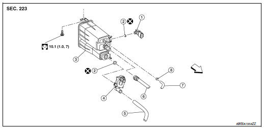
- EVAP control system pressure sensor
- O-ring
- EVAP canister
- EVAP canister vent control valve
- EVAP canister vent control valve hose
- EVAP vent line
- EVAP canister purge hose
- Clamp
 Front
Front
Removal and Installation
NOTE: The EVAP canister vent control valve and EVAP control system pressure sensor can be removed without removing the EVAP canister.
REMOVAL
- Disconnect the EVAP control system pressure sensor harness connector and the EVAP canister vent control valve harness connector.
- Remove EVAP canister filter (1) and place aside (
 ).
).
(2) : EVAP canister
: Front
- Disconnect the EVAP canister purge hose, the EVAP vent line, and the EVAP canister vent control valve hose.
- Remove the EVAP canister bolt.
- Remove the EVAP canister from the vehicle.
- Remove EVAP control system pressure sensor and EVAP canister vent control valve (if necessary).
INSTALLATION Installation is in the reverse order of removal.
Inspection
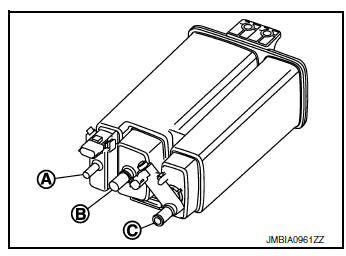
Check EVAP canister as follows:
- Block port (B).
- Blow air into port (A) and check that it flows freely out of port (C).
- Release blocked port (B).
- Apply vacuum pressure to port (B) and check that vacuum pressure exists at the ports (A) and (C).
- Block port (A) and (B).
- Apply pressure to port (C) and check that there is no leakage.
 Fuel tank
FWD
FWD : Exploded View
Fuel filler cap
Grommet
Fuel filler tube
Cover
Clamp
Fuel filler hose
Clamp
Vent hose
Fuel tank p ...
 EVAP canister vent control valve
Exploded View
EVAP control system pressure sensor
O-ring
EVAP canister
EVAP canister vent control valve
EVAP canister vent control valve hose
EVAP vent line
EVAP canister pu ...
Other materials:
How to follow trouble diagnoses
Description
NOTICE:
Trouble diagnoses indicate work procedures required to diagnose problems
effectively. Observe the following
instructions before diagnosing.
Before performing trouble diagnoses, read the “Work Flow” in each
section.
After repairs, re-check that the pr ...
Preparation
Commercial Service Tool
Tool name
Description
Brake drum clearance gauge
Measuring rear rotor drum inner diamete
Power tool
Loosening nuts, screws and bolts
...
Tire pressure sensor
Exploded View
Tire pressure sensor
O-ring
Valve stem nut
Valve core
Valve cap
Valve stem assembly
: Parts that are replaced as a
set when the tire is replaced.
Removal and Installation
REMOVAL
Remove wheel and tire using power tool.
Remove v ...
