Nissan Rogue Service Manual: Door switch
WITH INTELLIGENT KEY
WITH INTELLIGENT KEY : Component Function Check
1.CHECK FUNCTION
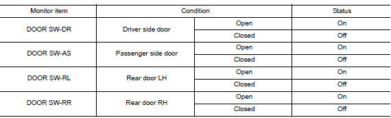
- Select "DOOR LOCK" of "BCM" using CONSULT.
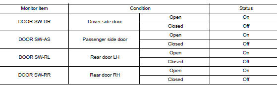
- Select "DOOR SW-DR", "DOOR SW-AS", "DOOR SW-RL", "DOOR SW-RR", in "Data Monitor" mode.
- Check that the function operates normally according to the following conditions.
Is the inspection result normal? YES >> Door switch is OK.
NO >> Refer to RF-34, "WITH INTELLIGENT KEY : Diagnosis Procedure".
WITH INTELLIGENT KEY : Diagnosis Procedure
Regarding Wiring Diagram information, refer to DLK-69, "Wiring Diagram".
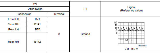
1.CHECK DOOR SWITCH INPUT SIGNAL
- Turn ignition switch OFF.
- Disconnect malfunctioning door switch connector.
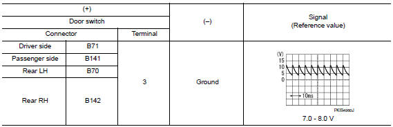
- Check signal between malfunctioning door switch harness connector and ground using oscilloscope.
Is the inspection result normal? YES >> GO TO 3.
NO >> GO TO 2.
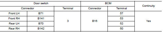
2.CHECK DOOR SWITCH CIRCUIT
- Disconnect BCM connector.
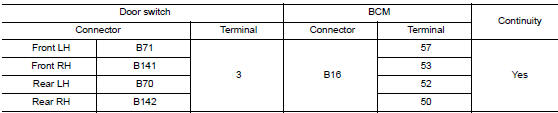
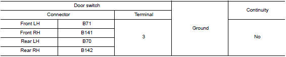
- Check continuity between door switch harness connector and BCM harness connector.
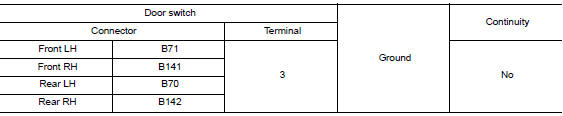
- Check continuity between door switch harness connector and ground.
Is the inspection result normal? YES >> Replace BCM. Refer to BCS-75, "Removal and Installation".
NO >> Repair or replace harness.
3.CHECK DOOR SWITCH
Refer to RF-35, "WITH INTELLIGENT KEY : Component Inspection".
Is the inspection result normal? YES >> GO TO 4.
NO >> Replace malfunctioning door switch. Refer to DLK-269, "Removal and Installation".
4.CHECK INTERMITTENT INCIDENT
Refer to GI-41, "Intermittent Incident".
>> Inspection End.
WITH INTELLIGENT KEY : Component Inspection
1.CHECK DOOR SWITCH
- Turn ignition switch OFF.
- Disconnect malfunctioning door switch connector.
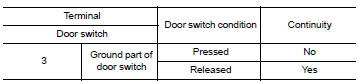
- Check continuity between door switch terminals.
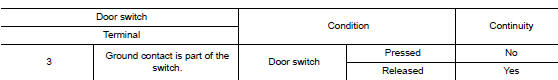
Is the inspection result normal? YES >> Inspection End.
NO >> Replace malfunctioning door switch. Refer to DLK-269, "Removal and Installation".
WITHOUT INTELLIGENT KEY
WITHOUT INTELLIGENT KEY : Description
Detects door open/close condition.
WITHOUT INTELLIGENT KEY : Component Function Check
1.CHECK FUNCTION
- Select "DOOR LOCK" of BCM using CONSULT.
- Select "DOOR SW-DR", "DOOR SW-AS", "DOOR SW-RL", "DOOR SW-RR", in Data Monitor mode.
- Check that the function operates normally according to the following conditions.
Is the inspection result normal? YES >> Door switch is OK.
NO >> Refer to RF-36, "WITHOUT INTELLIGENT KEY : Diagnosis Procedure".
WITHOUT INTELLIGENT KEY : Diagnosis Procedure
Regarding Wiring Diagram information, refer to DLK-293, "Wiring Diagram".
1.CHECK DOOR SWITCH INPUT SIGNAL
- Turn ignition switch OFF.
- Disconnect malfunctioning door switch connector.
- Check signal between malfunctioning door switch harness connector and ground using oscilloscope.
Is the inspection result normal? YES >> GO TO 3.
NO >> GO TO 2.
2.CHECK DOOR SWITCH CIRCUIT
- Disconnect BCM connector.
- Check continuity between door switch harness connector and BCM harness connector.
- Check continuity between door switch harness connector and ground.
Is the inspection result normal? YES >> Replace BCM. Refer to BCS-135, "Removal and Installation".
NO >> Repair or replace harness.
3.CHECK DOOR SWITCH
Refer to RF-35, "WITH INTELLIGENT KEY : Component Inspection".
Is the inspection result normal? YES >> GO TO 4.
NO >> Replace malfunctioning door switch. Refer to DLK-385, "Removal and Installation".
4.CHECK INTERMITTENT INCIDENT
Refer to GI-41, "Intermittent Incident".
>> Inspection End.
WITHOUT INTELLIGENT KEY : Component Inspection
1.CHECK DOOR SWITCH
- Turn ignition switch OFF.
- Disconnect door switch connector.
- Check door switch.
Is the inspection result normal? YES >> Inspection End.
NO >> Replace malfunctioning door switch. Refer to DLK-385, "Removal and Installation".
 Moonroof switch
Description
Transmits switch operation signal to moonroof motor and sunshade motor
assembly.
Diagnosis Procedure
Regarding Wiring Diagram information, refer to RF-17, "Wiring Diagram".
...

Other materials:
DTC/circuit diagnosis
U1000 CAN COMM CIRCUIT
Description
Refer to LAN-8, "System Description".
DTC Logic
DTC DETECTION LOGIC
NOTE:
U1000 can be set if a module harness was disconnected and reconnected, perhaps
during a repair. Confirm
that there are actual CAN diagnostic symptoms and a present DTC by p ...
Towing recommended by NISSAN
All-Wheel Drive (AWD) models
NISSAN recommends that towing dollies be
used when towing your vehicle or the vehicle be
placed on a flatbed truck as illustrated.
CAUTIONDO NOT tow AWD models with any of the
wheels on the ground as this may cause
serious and expensive damage to the ...
Power supply and ground circuit
BCM (BODY CONTROL SYSTEM) (WITH INTELLIGENT KEY SYSTEM)
BCM (BODY CONTROL SYSTEM) (WITH INTELLIGENT KEY SYSTEM) : Diagnosis
Procedure
Regarding Wiring Diagram information, refer to BCS-50, "Wiring Diagram".
1. CHECK FUSE
Check that the following fuse is not blown.
Is the fuse blo ...
