Nissan Rogue Service Manual: Moonroof switch
Description
Transmits switch operation signal to moonroof motor and sunshade motor assembly.
Diagnosis Procedure
Regarding Wiring Diagram information, refer to RF-17, "Wiring Diagram".
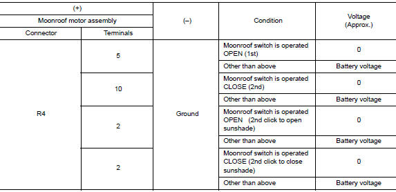
1.CHECK MOONROOF SWITCH INPUT SIGNAL
- Turn ignition switch ON.
- Check voltage between moonroof motor assembly harness connector and ground.
Is the inspection result normal? YES >> Inspection End.
NO >> GO TO 2.
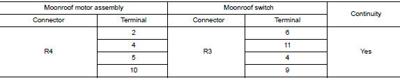
2.CHECK MOONROOF SWITCH CIRCUIT
- Turn ignition switch OFF.
- Disconnect moonroof motor assembly connector and moonroof switch connector.
- Check continuity between moonroof motor assembly harness connector and moonroof switch harness connector.
- Check continuity between moonroof motor assembly harness connector and ground.
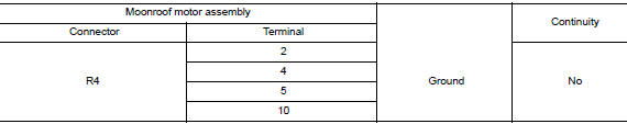
Is the inspection result normal? YES >> GO TO 3.
NO >> Repair or replace the harness.
3.CHECK MOONROOF SWITCH GROUND CIRCUIT
Check continuity between moonroof switch harness connector and ground.
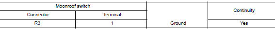
Is the inspection result normal? YES >> GO TO 4.
NO >> Repair or replace the harness.
4.CHECK MOONROOF SWITCH
Check moonroof switch.
Refer to RF-32, "Component Inspection".
Is the inspection result normal? YES >> GO TO 5.
NO >> Replace moonroof switch. Refer to RF-64, "Removal and Installation".
5.CHECK INTERMITTENT INCIDENT
Refer to GI-41, "Intermittent Incident".
>> Inspection End.
Component Inspection
MOONROOF SWITCH
1. CHECK MOONROOF SWITCH
- Turn ignition switch OFF.
- Disconnect moonroof switch.
- Check continuity between moonroof switch terminals.
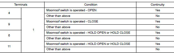
Is the inspection result normal? YES >> Moonroof switch is OK.
NO >> Replace moonroof switch. Refer to RF-64, "Removal and Installation".
 Power supply and ground circuit
BCM (BODY CONTROL SYSTEM) (WITH INTELLIGENT KEY SYSTEM)
BCM (BODY CONTROL SYSTEM) (WITH INTELLIGENT KEY SYSTEM) : Diagnosis
Procedure
Regarding Wiring Diagram information, refer to BCS-50, "Wi ...
 Door switch
WITH INTELLIGENT KEY
WITH INTELLIGENT KEY : Component Function Check
1.CHECK FUNCTION
Select "DOOR LOCK" of "BCM" using CONSULT.
Select "DOOR SW-DR", ...
Other materials:
P0743 torque converter
DTC Description
DTC DETECTION LOGIC
DTC
CONSULT screen terms
(Trouble diagnosis content)
DTC detection condition
P0743
TORQUE CONVERTER
(Torque Converter Clutch Circuit Electrical)
When all of the following conditions are satisfied and this state is
maintained ...
Precaution
Precaution for Supplemental Restraint System (SRS) "AIR BAG" and "SEAT
BELT
PRE-TENSIONER"
The Supplemental Restraint System such as “AIR BAG” and “SEAT BELT PRE-TENSIONER”,
used along
with a front seat belt, helps to reduce the risk or severity of injury to the
...
Recommended chemical products
and sealants
Refer to the following chart for help in selecting the appropriate chemical
product or sealant.
Product Description
Purpose
NISSAN North America
Part No. (USA)
NISSAN Canada Part
No. (Canada)
Aftermarket Crossreference
Part Nos.
1
Rear View Mirror ...
