Nissan Rogue Service Manual: Power supply and ground circuit
BCM (BODY CONTROL SYSTEM) (WITH INTELLIGENT KEY SYSTEM)
BCM (BODY CONTROL SYSTEM) (WITH INTELLIGENT KEY SYSTEM) : Diagnosis Procedure
Regarding Wiring Diagram information, refer to BCS-50, "Wiring Diagram".
1. CHECK FUSE
Check that the following fuse is not blown.

Is the fuse blown? YES >> Replace the blown fuse after repairing the affected circuit.
NO >> GO TO 2.
2. CHECK POWER SUPPLY CIRCUIT
- Disconnect BCM connector M20.
- Check voltage between BCM connector M20 and ground.
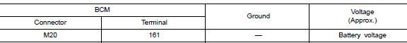
Is the inspection result normal? YES >> GO TO 3.
NO >> Repair or replace harness or connectors.
3. CHECK GROUND CIRCUIT
Check continuity between BCM connector M20 and ground.
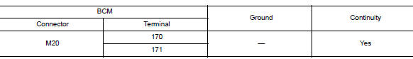
Is the inspection result normal? YES >> Inspection End.
NO >> Repair or replace harness or connectors.
BCM (BODY CONTROL SYSTEM) (WITHOUT INTELLIGENT KEY SYSTEM)
BCM (BODY CONTROL SYSTEM) (WITHOUT INTELLIGENT KEY SYSTEM) : Diagnosis Procedure
Regarding Wiring Diagram information, refer to BCS-110, "Wiring Diagram".
1. CHECK FUSE
Check that the following fuse is not blown.

Is the fuse blown? YES >> Replace the blown fuse after repairing the affected circuit.
NO >> GO TO 2.
2. CHECK POWER SUPPLY CIRCUIT
- Disconnect BCM connector M20.
- Check voltage between BCM connector M20 and ground.
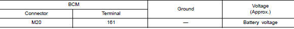
Is the inspection result normal? YES >> GO TO 3.
NO >> Repair or replace harness or connectors.
3. CHECK GROUND CIRCUIT
Check continuity between BCM connector M20 and ground.
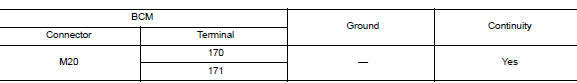
Is the inspection result normal? YES >> Inspection End.
NO >> Repair or replace harness or connectors.
MOONROOF MOTOR ASSEMBLY
MOONROOF MOTOR ASSEMBLY : Description
- BCM supplies the moonroof motor assembly with power.
- CPU is integrated in moonroof motor assembly.
- Tilts up/down & slides open/close by moonroof switch operation.
- In order to close the moonroof during high speed driving, the Combination meter will send a speed signal to the moonroof CPU to adjust the torque of the motor during the tilt-down operation.
MOONROOF MOTOR ASSEMBLY : Component Function Check
1. CHECK MOONROOF MOTOR FUNCTION
Does the tilt up/down & slide open/close functions operate normally with moonroof switch? Is the inspection result normal? YES >> Moonroof motor assembly is OK.
NO >> Refer to RF-26, "MOONROOF MOTOR ASSEMBLY : Diagnosis Procedure".
MOONROOF MOTOR ASSEMBLY : Diagnosis Procedure
Regarding Wiring Diagram information, refer to RF-17, "Wiring Diagram".
MOONROOF MOTOR ASSEMBLY
1. CHECK POWER SUPPLY CIRCUIT
- Turn ignition switch OFF.
- Disconnect the moonroof motor assembly connector.
- Turn ignition switch ON.
- Check voltage between moonroof motor assembly connector and ground.
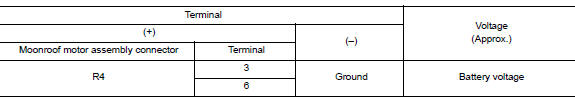
Is the inspection result normal? YES >> GO TO 2.
NO >> GO TO 3.
2. CHECK GROUND CIRCUIT
- Turn ignition switch OFF.
- Check continuity between moonroof motor assembly connector and ground.

Is the inspection result normal? YES >> GO TO 5.
NO >> Repair or replace harness.
3.CHECK HARNESS CONTINUITY
- Turn ignition switch OFF.
- Disconnect power window relay connector.
- Check continuity between power window relay harness connector and moonroof motor assembly harness connector.
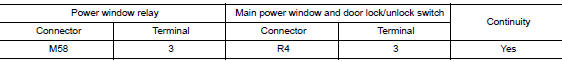
- Check continuity between power window relay harness connector and ground.
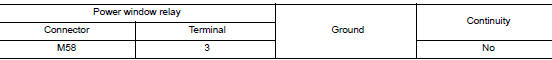
Is the inspection result normal? YES >> Refer to PWC-48, "Diagnosis Procedure".
NO >> Repair or replace harness.
4. CHECK MOONROOF SWITCH INPUT SIGNAL
- Connect moonroof motor assembly.
- Turn ignition switch ON.
- Check voltage between the moonroof motor assembly connector and ground.

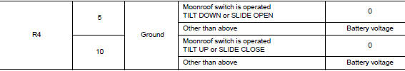
Is the inspection result normal? YES >> GO TO 8.
NO >> GO TO 6.
5. CHECK MOONROOF SWITCH CIRCUIT
- Turn ignition switch OFF.
- Disconnect the moonroof motor assembly and moonroof switch.
- Check continuity between the moonroof motor assembly connector and moonroof switch connector.
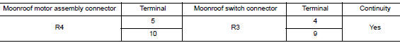
- Check continuity between the moonroof motor assembly connector and ground.
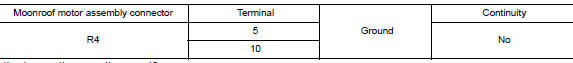
Is the inspection result normal? YES >> GO TO 7.
NO >> Repair or replace harness.
6. CHECK MOONROOF SWITCH GROUND CIRCUIT
- Connect moonroof motor assembly.
- Check continuity between the moonroof switch connector and ground.

Is the inspection result normal? YES >> Refer to RF-32, "Component Inspection".
NO >> Repair or replace harness.
7. CHECK COMBINATION METER SIGNAL
- Connect the moonroof motor assembly connector.
- Turn ignition switch ON.
- Check the signal between the moonroof motor assembly connector and ground with oscilloscope.
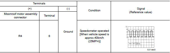
Is the inspection result normal? YES >> Replace moonroof motor assembly. Refer to RF-53, "Removal and Installation". After that, refer to RF-24, "ADDITIONAL SERVICE WHEN REPLACING CONTROL UNIT : Special Repair Requirement".
NO >> GO TO 9.
8.CHECK COMBINATION METER CIRCUIT
- Turn ignition switch OFF.
- Disconnect combination meter.
- Check continuity between the combination meter connector and the moonroof motor assembly connector.

- Check continuity between the combination meter connector and ground.

Is the inspection result normal? YES >> Replace combination meter. Refer to BCS-76, "Removal and Installation".
NO >> Repair or replace harness.
MOONROOF MOTOR ASSEMBLY : Special Repair Requirement
1. PERFORM INITIALIZATION PROCEDURE
Perform the initialization procedure.
Refer to RF-29, "MOONROOF MOTOR ASSEMBLY : Special Repair Requirement".
>> GO TO 2.
2. CHECK ANTI-PINCH OPERATION
Check the anti-pinch operation.
Refer to RF-29, "MOONROOF MOTOR ASSEMBLY : Special Repair Requirement".
Is the inspection result normal? YES >> Inspection End.
NO >> Check fitting adjustment.
SUNSHADE MOTOR ASSEMBLY
SUNSHADE MOTOR ASSEMBLY : Description
- BCM supplies the sunshade motor assembly with power.
- CPU is integrated in sunshade motor assembly.
- Slide open/close controlled by the moonroof switch operation.
SUNSHADE MOTOR ASSEMBLY : Component Function Check
1. CHECK SUNSHADE MOTOR FUNCTION
Does the slide open and close functions operate normally with the moonroof switch? Is the inspection result normal? YES >> Sunshade motor assembly is OK.
NO >> Refer to RF-29, "SUNSHADE MOTOR ASSEMBLY : Diagnosis Procedure".
SUNSHADE MOTOR ASSEMBLY : Diagnosis Procedure
1.CHECK POWER SUPPLY
- Turn ignition switch OFF.
- Disconnect sunshade motor assembly connector.
- Turn ignition switch ON.
- Check voltage between sunshade motor assembly harness connector and ground.
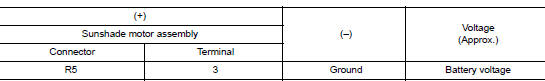
Is the inspection result normal? YES >> GO TO 2.
NO >> GO TO 3.
2.CHECK GROUND CIRCUIT
- Turn ignition switch OFF.
- Check continuity between sunshade motor assembly harness connector and ground.
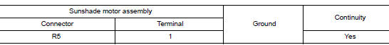
Is the inspection result normal? YES >> GO TO 4.
NO >> Repair or replace the harness.
3.CHECK HARNESS CONTINUITY
- Turn ignition switch OFF.
- Disconnect power window relay connector.
- Check continuity between power window relay harness connector and moonroof motor assembly harness connector.
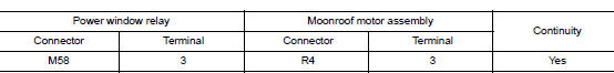
- Check continuity between power window relay harness connector and ground.
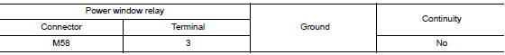
Is the inspection result normal? YES >> Refer to PWC-48, "Diagnosis Procedure".
NO >> Repair or replace harness.

 Moonroof switch
Description
Transmits switch operation signal to moonroof motor and sunshade motor
assembly.
Diagnosis Procedure
Regarding Wiring Diagram information, refer to RF-17, "Wiring Diagram".
...
Other materials:
Removal and installation
POWER SOCKET
Removal and Installation
FRONT POWER SOCKET
Removal
Remove cluster lid C. Refer to IP-21, "Removal and Installation".
Release the pawls on the power socket and remove from the cluster
lid C.
Installation
Installation is in the reverse order of remov ...
Symptom diagnosis
MULTI AV SYSTEM
Symptom Table
RELATED TO AUDIO
Symptoms
Check items
Probable malfunction location
The disk cannot be removed.
AV control unit
Malfunction in AV control unit.
Refer to AV-91, "On Board Diagnosis Function".
No sound comes ...
Symptom diagnosis
EXTERIOR LIGHTING SYSTEM SYMPTOMS
Symptom Table
CAUTION:
Perform the self-diagnosis with CONSULT before the symptom diagnosis. Perform
the trouble diagnosis
if any DTC is detected.
NORMAL OPERATING CONDITION
Description
AUTO LIGHT SYSTEM
The headlamp may not be turned ON/OFF immedi ...
