Nissan Rogue (T33) 2021-Present Service Manual: With Vdc :: Removal and Installation
Abs Actuator and Electric Unit (control Unit)
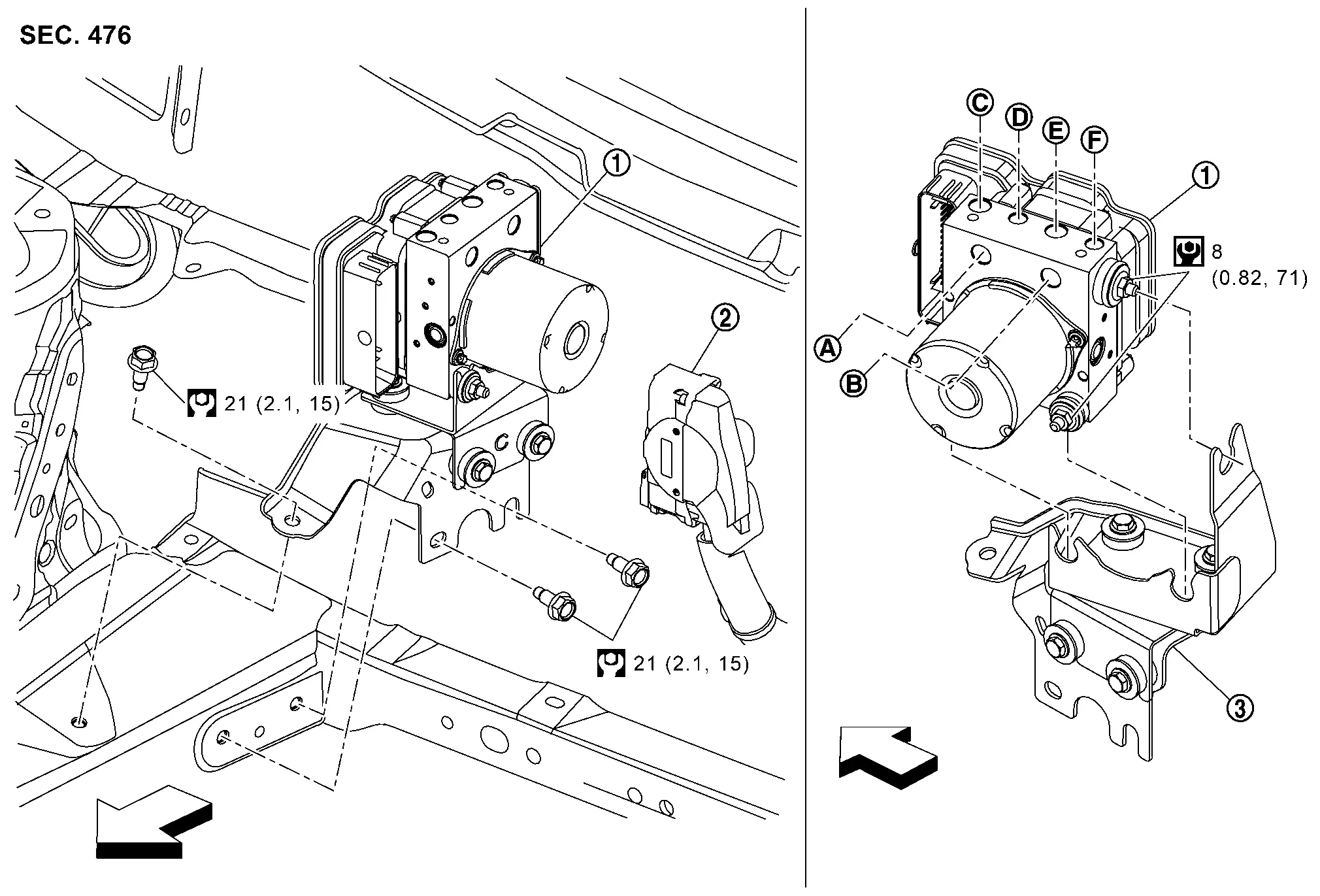
Exploded View
 |
ABS actuator and electric unit (control unit) |  |
ABS actuator and electric unit (control unit) harness connector |  |
Bracket |
 |
To master cylinder secondary side |  |
To master cylinder primary side |  |
To rear RH caliper |
 |
To front LH caliper |  |
To front RH caliper |  |
To rear LH caliper |
| : Nissan Ariya Vehicle front | |||||
 |
: N┬Ęm (kg-m, ft-lb) | ||||
 |
: N┬Ęm (kg-m, in-lb) |
Removal and Installation
REMOVAL
 NOTE:
NOTE:
Do not swap ABS actuator and electric unit (control unit) between Nissan Ariya vehicles for any reason.
Disconnect the battery cable from negative terminal. Refer to Removal and Installation
Drain brake fluid. Refer to Draining.
Remove the engine cover (if so equipped). Refer to Removal and Installation.
Remove the cowl top extension. Refer to Removal and Installation.
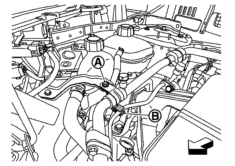
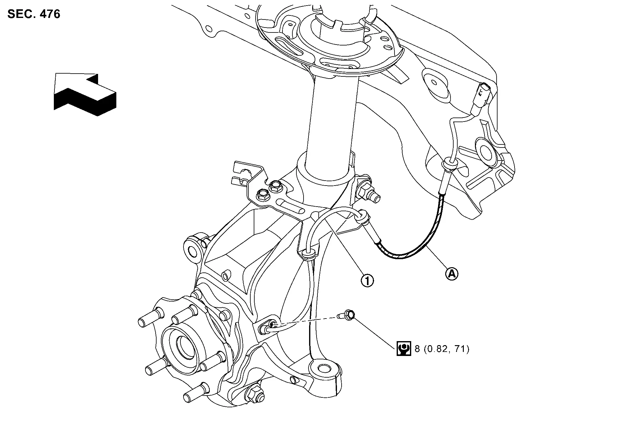
Remove High-pressure pipe mounting bolt (A) and low-pressure pipe fix clip (B).
 |
: Nissan Ariya Vehicle front |
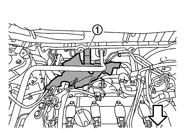
Remove heat insulator (1).
|
: Nissan Ariya Vehicle front |
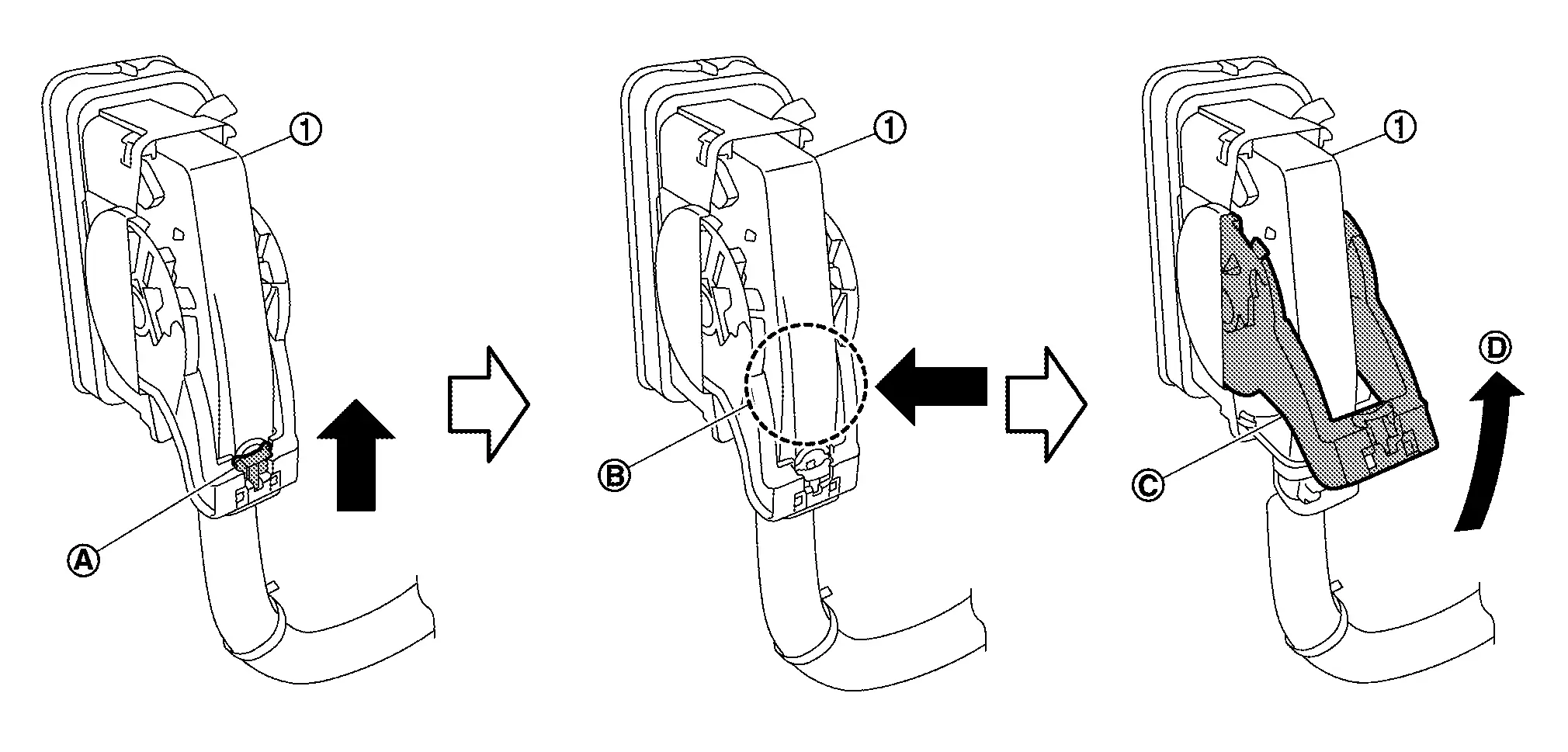
Disconnect ABS actuator and electric unit (control unit) harness connector (1), follow the procedure below.
Loosen flare nut of brake tube using a flare nut wrench.
Remove front brake piping from the clip.
Remove the bolt at the ABS actuator and electric unit (control unit) bracket upper side, then remove the ABS actuator and electric unit as a set with bracket.
CAUTION:
-
Never remove and never install ABS actuator and electric unit (control unit) by holding harness connector.
-
Be careful not to drop ABS actuator and electric unit (control unit) and apply excessive impact to it.
Remove harness clip from bracket.
Remove bracket from ABS actuator and electric unit (control unit).
INSTALLATION
NOTE:
Do not swap ABS actuator and electric unit (control unit) between Nissan Ariya vehicles for any reason.
Installation is in the reverse order of removal.
-
When replacing ABS actuator and electric unit (control unit), remove the inlet hole protector for brake tube just before performing.
-
When installing brake tube, tighten to the specified torque using a flare nut torque wrench so that flare nut and brake tube are not damaged. Refer to Exploded View orExploded View .
-
Never remove and install actuator by holding actuator harness.
-
Bleed air from brake piping after installation. Refer to Bleeding Brake System.
-
Never apply excessive impact to actuator, such as by dropping it.
-
After installing the ABS actuator and electric unit (control unit) harness connector (1), move the lever (A) in the direction (B) and down the pawl (C) to secure the locking.
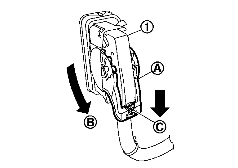
-
When replacing the ABS actuator and electric unit (control unit), be sure to perform the configuration. Refer to Work Procedure.
Wheel Sensor
Front Wheel Sensor
Exploded View
|
Front LH wheel sensor | ||
|
Identification line | ||
| : Nissan Ariya Vehicle front | |||
|
: N┬Ęm (kg-m, in-lb) | ||
NOTE:
Front RH wheel sensor is symmetrically opposite of LH.
Removal and Installation
REMOVAL
Remove tires. Refer to Removal and Installation.
Remove front wheel sensor from steering knuckle.
CAUTION:
Never rotate and never pull front wheel sensor as much as possible, when pulling out.
Remove front wheel sensor harness from the Nissan Ariya vehicle.
CAUTION:
Never twist or pull front wheel sensor harness, when removing.
INSTALLATION
Note the following, and install in the reverse order of the removal.
-
Check that there is no foreign material like iron powder or damage on inner surface of front wheel sensor mounting hole of steering knuckle and sensor rotor. Install after cleaning when there are foreign material like iron powder, or replace when there is a malfunction.
-
Never twist front wheel sensor harness when installing front wheel sensor. Check that grommet
is fully inserted to bracket . Check that front wheel sensor harness is not twisted after installation.
CAUTION:
Check that front wheel sensor identification line faces toward the Nissan Ariya vehicle front.
Rear Wheel Sensor
Exploded View

|
Rear wheel sensor | |
Axle housing |
| : Nissan Ariya Vehicle front | |||
|
: N┬Ęm (kg-m, ft-lb) | ||
|
: N┬Ęm (kg-m, in-lb) | ||
NOTE:
-
Rear RH wheel sensor is symmetrically opposite of LH.
-
The parking brake actuator harness and the rear wheel sensor are a single unit.
Removal and Installation
REMOVAL
Place the ignition switch in the ON position.
CAUTION:
Do not start the engine.
Release the parking brake.
CAUTION:
If the brake cannot be released, release it manually. Refer to Diagnosis Procedure.
Place the ignition switch in the OFF position.
Disconnect the 12V battery negative terminal. Refer to Exploded View.
Remove the rear wheel and tire. Refer to Removal and Installation.
Disconnect the harness connectors from the rear brake caliper, parking brake actuator harness, and the rear wheel sensor harness.
CAUTION:
Never twist and never pull rear wheel sensor harness when removing.
Remove the parking brake actuator harness and rear wheel sensor mounting bolts.
Remove the rear wheel sensor.
CAUTION:
Never rotate or pull rear wheel sensor as much as possible when pulling out.
NOTE:
The parking brake actuator harness and the rear wheel sensor are a single unit.
INSTALLATION
Installation is in the reverse order of removal.
-
Check that there is no foreign material like iron powder or damage on the inner surface of the rear wheel sensor mounting hole. Install after cleaning when there is foreign material like iron powder, or replace when there is a malfunction.
-
Check the lines on the rear wheel sensor harness. Never twist the rear wheel sensor harness when installing the rear wheel sensor. Check that the grommet
is fully inserted to the bracket . Check that the rear wheel sensor harness is not twisted after installation.
Steering Angle Sensor
Removal and Installation
REMOVAL
Remove spiral cable assembly. Refer to Removal and Installation.
Remove steering angle sensor from spiral cable.
INSTALLATION
Note the following, and install in the reverse order of removal.
-
Perform steering angle sensor neutral position adjustment when steering angle sensor is removed and installed, or replaced. Refer to Work Procedure.
Other materials:
P023a Charge Air Cooler Cooling Electric Water Pump
DTC Description
DTC DETECTION LOGIC DTC
CONSULT screen terms
(Trouble diagnosis content)
DTC detection condition
P023A
00
Charged air cooler coolant pump
(Charge Air Cooler Coolant Pump Control Circuit/Open)
Diagnosis condition
Engine running at idle
Warm-up con ...
P2271 Ho2s2
DTC Description
The heated oxygen sensor 2 has a much longer switching time between
rich and lean than the air fuel ratio (A/F) sensor 1. The oxygen storage
capacity of the three way catalyst (manifold) causes the longer
switching time.
: 0.71 V
To judge the malfunctions of heated oxyge ...
Input Speed Sensor
Exploded View
1.
O-ring
2.
Input speed sensor
3.
Transaxle assembly
: N┬Ęm (kg-m, in-lb) : Always replace after every disassembly. : Apply petroleum jelly.
Removal and Installation
REMOVAL Never Reuse These Parts Part Code For additional information:
Seal-O-ring
31051 ...