Nissan Rogue Service Manual: Wiring diagram
STARTING SYSTEM
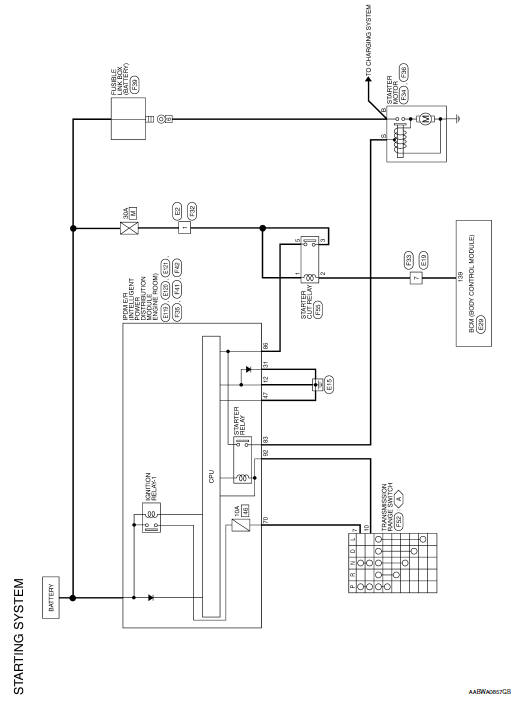
Wiring Diagram
 System
System Description
The starter motor plunger closes and provides a closed circuit between the
battery and the starter motor. The
starter motor is grounded to the cylinder block. With power and gro ...
 Basic inspection
DIAGNOSIS AND REPAIR WORKFLOW
Work Flow (With GR8-1200 NI)
STARTING SYSTEM DIAGNOSIS WITH GR8-1200 NI
To test the starting system, use the following special service tool:
GR8-1200 NI Mult ...
Other materials:
Connector Symbols
Most of connector symbols in wiring diagrams are shown from the terminal
side.
Connector symbols shown from the terminal side are enclosed by
a single line and followed by the direction mark.
Connector symbols shown from the harness side are enclosed by
a double line and foll ...
DTC/circuit diagnosis
DOOR MIRROR REMOTE CONTROL SWITCH (MIRROR SWITCH/
CHANGEOVER SWITCH)
Component Inspection
1.CHECK MIRROR SWITCH & CHANGEOVER SWITCH
Turn ignition switch OFF.
Disconnect door mirror remote control switch connector.
Check door mirror remote control switch.
Is th ...
DTC/circuit diagnosis
P1610 LOCK MODE
Description
ECM forcibly switches to the mode that inhibits engine start, when engine
start operation is performed 5 times
or more while communication between ECM and BCM is not normal.
DTC Logic
DTC DETECTION LOGIC
NOTE:
If DTC B1610 is displayed with DTC U1000, fi ...
