Nissan Rogue Service Manual: Basic inspection
DIAGNOSIS AND REPAIR WORKFLOW
Work Flow (With GR8-1200 NI)
STARTING SYSTEM DIAGNOSIS WITH GR8-1200 NI
To test the starting system, use the following special service tool:
- GR8-1200 NI Multitasking battery and electrical diagnostic station
NOTE: Refer to the diagnostic station Instruction Manual for proper starting system diagnosis procedures.
OVERALL SEQUENCE
DETAILED FLOW
NOTE: To ensure a complete and thorough diagnosis, the battery, starter motor and generator test segments must be done as a set from start to finish.
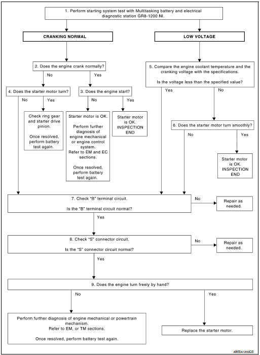
1.DIAGNOSIS WITH MULTITASKING BATTERY AND ELECTRICAL DIAGNOSTIC STATION GR8-1200 NI
Perform the starting system test with Multitasking battery and electrical diagnostic station GR8-1200 NI. For details and operating instructions, refer to diagnostic station Instruction Manual.
Test result CRANKING NORMAL>>GO TO 2.
LOW VOLTAGE>>GO TO 5.
CHARGE BATTERY>>Perform the slow battery charging procedure. (Initial rate of charge is 10A for 12 hours.) Perform battery test again. Refer to diagnostic station instruction manual.
REPLACE BATTERY>>Before replacing battery, clean the battery cable clamps and battery posts. Perform battery test again. Refer to diagnostic station instruction manual. If second test result is ÔÇťREPLACE BATTERYÔÇŁ, then do so. Perform battery test again to confirm repair.
2.CRANKING CHECK
Check that the starter motor operates properly.
Does the engine crank normally? YES >> GO TO 3.
NO >> GO TO 4.
3.ENGINE START CHECK
Check that the engine starts.
Does the engine start? YES >> Inspection End.
NO >> Perform further diagnosis of engine mechanical or engine control system. Refer to EM and EC sections. Once resolved, perform battery test again.
4.STARTER MOTOR ACTIVATION
Check that the starter motor operates.
Does the starter motor turn? YES >> Check ring gear and starter motor drive pinion. Once resolved, perform battery test again.
NO >> GO TO 7.
5.COMPARISON BETWEEN ENGINE COOLANT AND CRANKING VOLTAGE
Compare the engine coolant temperature and verify the cranking voltage is within specifications.
Minimum Specification of Cranking Voltage Referencing Coolant Temperature
| Engine coolant temperature [┬░C (┬░F)] | Voltage [V] |
| Ôłĺ30 to Ôłĺ20 (Ôłĺ22 to Ôłĺ4) | 8.6 |
| Ôłĺ19 to Ôłĺ10 (Ôłĺ2 to 14) | 9.1 |
| Ôłĺ19 to Ôłĺ10 (Ôłĺ2 to 14) | 9.5 |
| More than 1 (More than 34) | 9.9 |
Is the voltage less than the specified value? YES >> GO TO 7.
NO >> GO TO 6.
6.STARTER OPERATION
Check the starter operation.
Does the starter motor turn smoothly? YES >> Inspection End.
NO >> GO TO 7.
7.ÔÇťBÔÇŁ TERMINAL CIRCUIT INSPECTION
Check ÔÇťBÔÇŁ terminal circuit. Refer to STR-17, "Diagnosis Procedure".
Is ÔÇťBÔÇŁ terminal circuit normal? YES >> GO TO 8.
NO >> Repair as needed.
8.ÔÇťSÔÇŁ CONNECTOR CIRCUIT INSPECTION
Check ÔÇťSÔÇŁ connector circuit. Refer to STR-19, "Diagnosis Procedure"
Is ÔÇťSÔÇŁ connector circuit normal? YES >> GO TO 9.
NO >> Repair as needed.
9.ENGINE ROTATION STATUS
Check that the engine can be rotated by hand.
Does the engine turn freely by hand? YES >> Replace starter motor.
NO >> Perform further diagnosis of engine mechanical or powertrain mechanism. Once resolved, perform battery test again using Multitasking battery and electrical diagnostic station GR8-1200 NI.
Refer to the diagnostic station Instruction Manual for proper testing procedures.
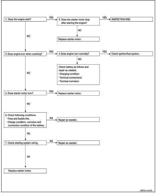
Work Flow (Without GR8-1200 NI)
OVERALL SEQUENCE
DETAILED FLOW
NOTE: If any malfunction is found, immediately disconnect the battery cable from the negative terminal.
1.CHECK ENGINE START
Crank the engine and check that the engine starts.
Does the engine start? YES >> GO TO 2.
2.CHECK THAT THE STARTER MOTOR STOPS
Check that the starter motor stops after starting the engine.
Does the starter motor stop? YES >> Inspection End.
NO >> Replace starter motor. Refer to STR-21, "Removal and Installation".
3.CHECK THAT THE ENGINE TURNS WHEN CRANKING
Check that the engine turns when cranking.
Does engine turn when cranking? YES >> GO TO 4.
NO >> GO TO 5.
4.CHECK THE ENGINE SPEED WHEN CRANKING
Check that the engine speed is not low when cranking.
Does engine turn normally? YES >> Check ignition/fuel system.
NO >> Check charge condition, corrosion and connection condition of the battery.
5.CHECK STARTER MOTOR ACTIVATION
Check that the starter motor runs at cranking.
Does starter motor turn? YES >> Replace starter motor. Refer to STR-21, "Removal and Installation".
NO >> GO TO 6.
6.CHECK POWER SUPPLY CIRCUIT
Check the following conditions:
- Fuse and fusible link
- Charge condition, corrosion and connection of the battery.
Are these inspection results normal? YES >> GO TO 7.
NO >> Repair as needed.
7.CHECK STARTING SYSTEM WIRING
Check the following:
- ÔÇťBÔÇŁ terminal circuit. Refer to STR-17, "Diagnosis Procedure".
- ÔÇťSÔÇŁ terminal circuit. Refer to STR-19, "Diagnosis Procedure".
Are the inspection results normal? YES >> Replace starter motor. Refer to STR-21, "Removal and Installation".
NO >> Repair as needed.
 Wiring diagram
STARTING SYSTEM
Wiring Diagram
...

Other materials:
Warning systems switch (if so equipped)
Warning systems switch (if so equipped)
The warning systems switch is used to turn on
and off the warning systems (Lane Departure
Warning (LDW), Forward Collision Warning
(FCW) and Blind SpotWarning (BSW) systems)
that are activated using the settings menu on the
vehicle information displa ...
Heating and cooling unit assembly
Exploded View
Steering Member
Heating and cooling unit assembly
Steering member
Bolt
Nut
Automatic Air Conditioning
Wiring harness
Air mix door duct (LH)
Air mix door duct (RH)
Intake housing gasket
Blower motor
Front foot duct (RH)
...
Bluetooth® Hands-Free Phone System
voice commands
To access the Bluetooth® Hands-Free Phone
System voice commands:
Press the button.
Say ÔÇťCallÔÇŁ and then a name in the vehicle
phonebook to call that entry. Otherwise, say
ÔÇťPhoneÔÇŁ to access various phone commands.
If the Bluetooth┬« has been set to ÔÇťOffÔÇŁ, the
s ...
