Nissan Rogue Owners Manual: Warning systems switch (if so equipped)
Warning systems switch (if so equipped)
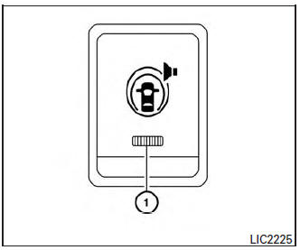
The warning systems switch is used to turn on and off the warning systems (Lane Departure Warning (LDW), Forward Collision Warning (FCW) and Blind SpotWarning (BSW) systems) that are activated using the settings menu on the vehicle information display.
When the warning systems switch is turned off, the indicator 1 on the switch is off. The indicator will also be off if all of the warning systems are deactivated using the settings menu.
The LDW system will sound a warning chime and blink the LDW indicator light (orange) to alert the driver if the vehicle is traveling close to either the left or the right of a traveling lane with detectable lane markers. For additional information, refer to “Lane Departure Warning (LDW) system” in the “Starting and driving” section of this manual.
The BSW system will turn on the BSW indicator light, located next to the outside mirrors, if the camera detects a vehicle in the detection zone. If the turn signal is activated in the direction of the detected vehicle, a chime sounds twice and the BSW indicator light will flash. For additional information, refer to “Blind Spot Warning (BSW) system” in the “Starting and driving” section of this manual.
 Hill descent control switch (if so equipped)
Hill descent control switch (if so equipped)
WARNING
Never rely solely on the hill descent
control system to control vehicle speed
when driving on steep downhill grades.
...
 Power outlets
Instrument Panel
12V OUTLETS
The power outlets are for powering electrical
accessories such as cellular telephones. They
are rated at 12 volt, 120W (10A) maximum.
The front and center conso ...
Other materials:
C1729 vehicle speed signal
DTC Logic
NOTE:
The Signal Tech II Tool [- (J-50190)] can be used to perform the following
functions. Refer to the Signal Tech II
User Guide for additional information.
Activate and display TPMS sensor IDs
Display tire pressure reported by the TPMS sensor
Read TPMS DTC ...
CAN system (type 7)
MAIN LINE BETWEEN IPDM-E AND DLC CIRCUIT
Diagnosis Procedure
1.CHECK CONNECTOR
Turn the ignition switch OFF.
Disconnect the battery cable from the negative terminal.
Check the following terminals and connectors for damage, bend and
loose connection (connector side
an ...
Changing engine oil
Changing engine oil
Park the vehicle on a level surface and apply
the parking brake.
Start the engine and let it idle until it reaches
operating temperature, then turn it off.
Remove the oil filler cap B by turning it
counterclockwise.
Place a large drain pan u ...
