Nissan Rogue Owners Manual: Front power seat adjustment (if so equipped)
Operating tips
- The power seat motor has an auto-reset overload protection circuit. If the motor stops during operation, wait 30 seconds then reactivate the switch.
- Do not operate the power seat switch for a
long period of time when the engine is off.
This will discharge the battery.
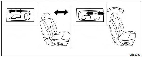
Forward and backward
Moving the switch forward or backward will slide the seat forward or backward to the desired position.
Reclining
Move the recline switch backward until the desired angle is obtained. To bring the seatback forward again, move the switch forward and move your body forward. The seatback will move forward.
The reclining feature allows adjustment of the seatback for occupants of different sizes for added comfort and to help obtain proper seat belt fit. For additional information, refer to ŌĆ£Precautions on seat belt usageŌĆØ in this section. Also, the seatback can be reclined to allow occupants to rest when the vehicle is stopped and the shift lever is in P (Park).
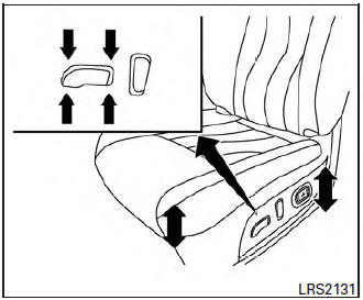
Seat lifter (driverŌĆÖs seat)
Push the switch up or down to achieve desired seat height.
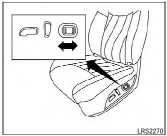
Lumbar support (driverŌĆÖs seat)
The lumbar support feature provides adjustable lower back support to the driver. Move the switch forward or backward to adjust the seatback lumbar area.
 Front manual seat adjustment
(if so equipped)
Front manual seat adjustment
(if so equipped)
Forward and backward
Pull the center of the bar up and hold it while you
slide the seat forward or backward to the desired
position. Release the bar to lock the seat in
position.
Reclining
...
 2nd row bench seat adjustment
Outboard seats
Forward and backward
Pull the center of the bar 1 up and hold it while
you slide the seat forward or backward to the
desired position. Release the bar to lock the seat
in posit ...
Other materials:
Air bag diagnosis sensor unit
Exploded View
Diagnosis sensor unit
Front
Removal and Installation
WARNING:
Before servicing the SRS, turn ignition switch OFF, disconnect
both battery terminals then wait at
least three minutes.
Before disconnecting the air bag diagnosis sensor unit harness
...
System
ENGINE CONTROL SYSTEM
ENGINE CONTROL SYSTEM : System Description
SYSTEM DIAGRAM
SYSTEM DESCRIPTION
ECM controls the engine by various functions.
Function
Reference
Multiport fuel injection system
EC-34, "MULTIPORT FUEL INJECTION SYSTEM : System Description
(wit ...
Brake master cylinder
Exploded View
Reservoir cap
Oil strainer
Reservoir tank
Brake fluid level sensor
Cylinder body
Pin
O-ring
Grommet
: Apply PBC (Poly Butyl
Cuprysil) grease or silicone-based grease.
: Apply brake fluid.
Removal and Installation
REMOVAL
CAUTION:
Do ...
