Nissan Rogue Service Manual: Brake master cylinder
Exploded View
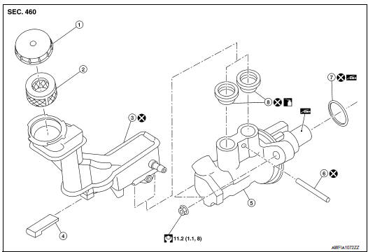
- Reservoir cap
- Oil strainer
- Reservoir tank
- Brake fluid level sensor
- Cylinder body
- Pin
- O-ring
- Grommet
 : Apply PBC (Poly Butyl
Cuprysil) grease or silicone-based grease.
: Apply PBC (Poly Butyl
Cuprysil) grease or silicone-based grease.
 : Apply brake fluid.
Removal and Installation
REMOVAL
CAUTION:
- Do not spill or splash brake fluid on painted areas; it may cause paint damage. If brake fluid is splashed on painted areas, wash it away with water immediately.
- Do not reuse master cylinder O-rings.
- Do not reuse drained brake fluid.
NOTE: When removing components such as hoses, tubes/lines, etc., cap or plug openings to prevent fluid from spilling.
- Remove air duct assembly to the electronic throtttle control actuator and air cleaner case (upper). Refer to EM-24, "Removal and Installation".
- Disconnect the harness connector from the brake fluid level sensor.
- Disconnect the hose from the reservoir tank.
- Disconnect the brake pipes from the master cylinder assembly with
a flare nut wrench.
CAUTION: Do not scratch the flare nut or the brake pipe.
- Remove the master cylinder assembly.
CAUTION: Do not depress the brake pedal after the master cylinder assembly is removed.
INSTALLATION
CAUTION:
- Do not spill or splash brake fluid on painted areas; it may cause paint damage. If brake fluid is splashed on painted areas, wash it away with water immediately.
- Do not reuse O-ring.
Installation is in the reverse order of removal.
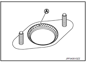
- Apply PBC (Poly Butyl Cuprysil) silicone-based grease to the brake booster (A) when installing the master cylinder assembly to the brake booster.
- Temporarily tighten the brake tube flare nut to the master
cylinder
assembly by hand. Then tighten it to the specified torque with a
flare nut crowfoot and torque wrench. Refer to BR-27, "Exploded
View".
CAUTION: Do not scratch the flare nut or the brake pipe.
- After installation, perform the air bleeding. Refer to BR-16, "Bleeding Brake System".
Disassembly and Assembly
DISASSEMBLY
CAUTION:
- Do not disassemble the cylinder body.
- Remove the reservoir tank only when necessary.
- Do not drop removed parts. The parts must not be reused if they are dropped.
- Secure the master cylinder assembly in a vise.
CAUTION: Always use copper plates or cloth between vise and cylinder body. Do not overtighten the vise.
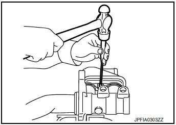
- Remove the reservoir tank pin using suitable tools.
CAUTION: Do not reuse the pin.
- Remove the reservoir tank and grommets from the cylinder body. Discard the grommets.
CAUTION:
- Do not drop parts. Dropped parts must not be reused.
- Do not reuse the grommets.
ASSEMBLY
- Apply new brake fluid to the grommets and install them to the
cylinder body.
CAUTION: Do not use mineral oil such as gasoline or light oil.
- Install the reservoir tank to the cylinder body.
CAUTION: Do not drop the parts during installation. The parts must not be reused if they are dropped.
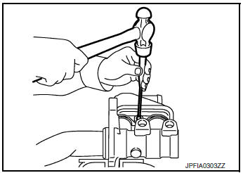
- Tilt the reservoir tank so that the pin can be inserted. Insert a pin
using suitable tools.
CAUTION: Do not reuse the pin.
 Brake piping
FRONT
FRONT : Exploded View
Master cylinder secondary to
ABS actuator brake tube
Master cylinder primary to
ABS actuator brake tube
Brake tube bracket
Brake tube (LH)
Brake ...
 Brake booster
Exploded View
Spacer
Gasket
Brake booster
Check valve
Reservoir tank
Brake fluid level sensor
Brake booster pressure sensor
Removal and installation
REMOVAL
...
Other materials:
P2096, P2097 A/F sensor 1
DTC Description
DTC DETECTION LOGIC
DTC No.
CONSULT screen terms
(Trouble diagnosis content)
DTC detecting condition
P2096
POST CATALYST FUEL TRIM SYS B1
(Post catalyst fuel trim system too lean bank
1)
The output voltage computed by ECM from the A/F sensor 1 s ...
P1805 brake switch
DTC Description
DTC DETECTION LOGIC
DTC No.
CONSULT screen terms
(Trouble diagnosis content)
DTC detecting condition
P1805
BRAKE SW/CIRCUIT
(BRAKE SW/CIRCUT)
A stop lamp switch signal is not sent to ECM for extremely long time
while
the vehicle is driving.
...
Door sash molding
Exploded View
Front door sash molding
Rear door rear sash molding
Front door panel
Rear door panel
Roof rail side outer
Body side outer
Rear door weather strip
Rear door glass
Removal and Installation
FRONT DOOR
Removal
Remove door mirror. Refer to MIR-22, &q ...
