Nissan Rogue Service Manual: Brake booster
Exploded View
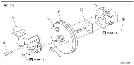
- Spacer
- Gasket
- Brake booster
- Check valve
- Reservoir tank
- Brake fluid level sensor
- Brake booster pressure sensor
Removal and installation
REMOVAL
- Remove the cowl top. Refer to EXT-25, "Removal and Installation".
- Remove the instrument lower panel LH. Refer to IP-22, "Removal and Installation".
- Remove the knee protector. Refer to IP-14, "Exploded View".
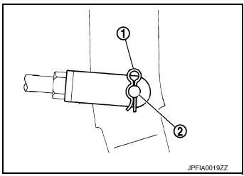
- Remove the snap pin (1) and clevis pin (2) from the brake pedal.
- Disconnect vacuum hose from brake booster. Refer to BR-32, "Exploded View".
- Remove master cylinder assembly. Refer to BR-27, "Removal and Installation".
- Disconnect the harness connector from the brake booster pressure sensor.
- Remove the brake booster pressure sensor.
- Remove the nuts on the brake booster and brake pedal.
CAUTION: Secure the brake booster to avoid damage to components.
- Remove the brake booster.
CAUTION: Do not deform or bend the brake pipes.
INSTALLATION
- Install a new gasket between the brake booster and dash panel.
CAUTION: Do not reuse the gasket.
- Install the brake booster to the dash panel from the engine room
side.
CAUTION: Do not damage brake booster stud bolt threads during installation.
- Install the nuts to the brake booster and brake pedal. Refer to BR-30, "Exploded View".
- Install the brake booster pressure sensor.
- Connect the harness connector to the brake booster pressure sensor.
- Install master cylinder assembly. Refer to BR-27, "Removal and Installation".
- Connect vacuum hose to brake booster. Refer toBR-32, "Exploded View".
- Install the clevis pin and snap pin to the brake pedal.
- Adjust the brake pedal. Refer to BR-15, "Adjustment".
- Install the knee protector. Refer to IP-14, "Exploded View".
- Install instrument lower panel LH. Refer to IP-22, "Removal and Installation".
- Bleed the brake system. Refer to BR-16, "Bleeding Brake System".
- Inspect the brake booster. Refer to BR-10, "Inspection".
 Brake master cylinder
Exploded View
Reservoir cap
Oil strainer
Reservoir tank
Brake fluid level sensor
Cylinder body
Pin
O-ring
Grommet
: Apply PBC (Poly Butyl
Cuprysil) grease or sil ...
 Vacuum lines
Exploded View
Clamp
Vacuum hose
Vacuum tube
Clip
Vacuum hose
To intake manifold
To brake booster
Paint mark
Stamp indicating engine direction
Removal an ...
Other materials:
Preparation
Commercial Service Tool
Tool name
Description
Brake drum clearance gauge
Measuring rear rotor drum inner diamete
Power tool
Loosening nuts, screws and bolts
...
Preparation
Special Service Tools
The actual shape of the tools may differ from those illustrated here.
Tool number
(Kent-Moore No.)
Tool name
Description
(J-44321)
Fuel pressure gauge
kit
Checks fuel pressure
KV10120000
Fuel tube adapter
...
Low tire pressure warning lamp
Component Function Check
1.CHECK THE ILLUMINATION OF THE LOW TIRE PRESSURE WARNING LAMP
Check that the low tire pressure warning lamp is turned OFF after
illuminating for approximately 1 second,
when the ignition switch is turned ON.
Is the inspection result normal?
YES >> Inspection ...
