Nissan Rogue Service Manual: Washer motor circuit
Diagnosis Procedure
Regarding Wiring Diagram information, refer to WW-22, "Wiring Diagram".
1. CHECK FRONT AND REAR WASHER MOTOR FUSE
- Turn the ignition switch OFF.
- Check that the following fuse is not blown.

Is the fuse blown? YES >> Replace the blown fuse after repairing the affected circuit.
NO >> GO TO 2.
2. CHECK FRONT AND REAR WASHER MOTOR POWER SUPPLY
- Disconnect front and rear washer motor.
- Turn ignition switch ON.
- Check voltage between front and rear washer motor harness connector and ground.
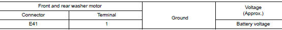
Is the inspection result normal? YES >> GO TO 3.
NO >> Repair or replace the harness or connectors.
3. CHECK FRONT AND REAR WASHER MOTOR CIRCUIT CONTINUITY
- Turn the ignition switch OFF.
- Disconnect combination switch (wiper and washer switch).
- Check continuity between combination switch (wiper and washer switch) harness connector and front and rear washer motor.
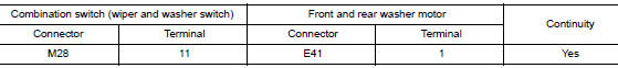
Is the inspection result normal? YES >> GO TO 4.
NO >> Repair or replace the harness or connectors.
4. CHECK WIPER AND WASHER SWITCH GROUND CIRCUIT
Check continuity between combination switch (wiper and washer switch) harness connector and ground.
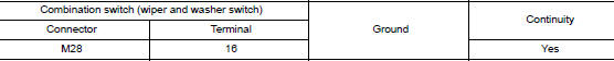
Is the inspection result normal? YES >> GO TO 5.
NO >> Repair or replace the harness or connectors.
5. CHECK WIPER AND WASHER SWITCH
Check wiper and washer switch. Refer to WW-45, "Component Inspection".
Is the inspection result normal? YES >> Replace front and rear washer motor. Refer to WW-57, "Removal and Installation".
NO >> Replace wiper and washer switch. Refer to BCS-76, "Removal and Installation".
 Front wiper motor ground circuit
Diagnosis Procedure
Regarding Wiring Diagram information, refer to WW-22, "Wiring Diagram".
1. CHECK FRONT WIPER MOTOR GROUND CIRCUIT
Turn the ignition switch OFF.
Discon ...
 Washer switch
Description
Washer switch is integrated with the combination switch.
Combination switch (wiper and washer switch) switches polarity
between front washer operating and rear
washer oper ...
Other materials:
ECU diagnosis information
EPS CONTROL UNIT
Reference Value
VALUES ON THE DIAGNOSIS TOOL
CAUTION:
The output signal indicates the EPS control unit calculation data. The normal
values will be displayed
even in the event that the output circuit (harness) is open.
NOTE:
The following table includes information (items) ...
Precaution
Precaution for Supplemental Restraint System (SRS) "AIR BAG" and "SEAT
BELT
PRE-TENSIONER"
The Supplemental Restraint System such as “AIR BAG” and “SEAT BELT
PRE-TENSIONER”, used along
with a front seat belt, helps to reduce the risk or severity of injury to the
...
Door switch
WITH INTELLIGENT KEY
WITH INTELLIGENT KEY : Component Function Check
1.CHECK FUNCTION
Select "DOOR LOCK" of "BCM" using CONSULT.
Select "DOOR SW-DR", "DOOR SW-AS", "DOOR SW-RL", "DOOR SW-RR", in
"Data Monitor&quo ...
