Nissan Rogue Service Manual: Door switch
WITH INTELLIGENT KEY
WITH INTELLIGENT KEY : Component Function Check
1.CHECK FUNCTION
- Select "DOOR LOCK" of "BCM" using CONSULT.
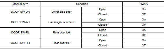
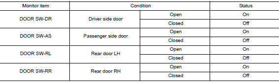
- Select "DOOR SW-DR", "DOOR SW-AS", "DOOR SW-RL", "DOOR SW-RR", in "Data Monitor" mode.
- Check that the function operates normally according to the following conditions.
Is the inspection result normal? YES >> Door switch is OK.
NO >> Refer to PWC-50, "WITH INTELLIGENT KEY : Diagnosis Procedure".
WITH INTELLIGENT KEY : Diagnosis Procedure
Regarding Wiring Diagram information, refer to DLK-69, "Wiring Diagram".
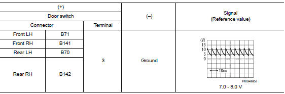
1.CHECK DOOR SWITCH INPUT SIGNAL
- Turn ignition switch OFF.
- Disconnect malfunctioning door switch connector.
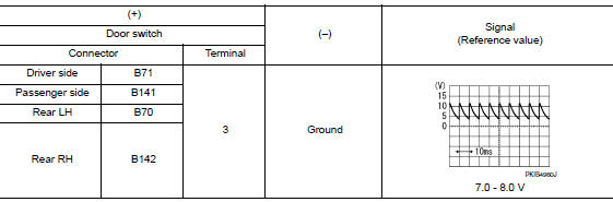
- Check signal between malfunctioning door switch harness connector and ground using oscilloscope.
Is the inspection result normal? YES >> GO TO 3.
NO >> GO TO 2.
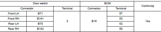
2.CHECK DOOR SWITCH CIRCUIT
- Disconnect BCM connector.
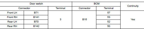
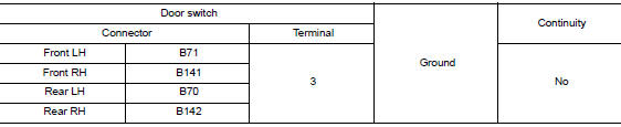
- Check continuity between door switch harness connector and BCM harness connector.
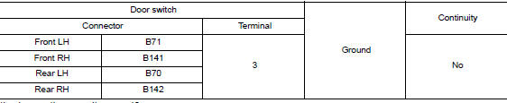
- Check continuity between door switch harness connector and ground.
Is the inspection result normal? YES >> Replace BCM. Refer to BCS-75, "Removal and Installation".
NO >> Repair or replace harness.
3.CHECK DOOR SWITCH
Refer to PWC-51, "WITH INTELLIGENT KEY : Component Inspection".
Is the inspection result normal? YES >> GO TO 4.
NO >> Replace malfunctioning door switch. Refer to DLK-269, "Removal and Installation".
4.CHECK INTERMITTENT INCIDENT
Refer to GI-41, "Intermittent Incident".
>> Inspection End.
WITH INTELLIGENT KEY : Component Inspection
1.CHECK DOOR SWITCH
- Turn ignition switch OFF.
- Disconnect malfunctioning door switch connector.
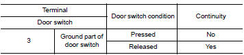
- Check continuity between door switch terminals.
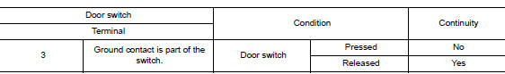
Is the inspection result normal? YES >> Inspection End.
NO >> Replace malfunctioning door switch. Refer to DLK-269, "Removal and Installation".
WITHOUT INTELLIGENT KEY
WITHOUT INTELLIGENT KEY : Description
Detects door open/close condition.
WITHOUT INTELLIGENT KEY : Component Function Check
1.CHECK FUNCTION
- Select "DOOR LOCK" of BCM using CONSULT.
- Select "DOOR SW-DR", "DOOR SW-AS", "DOOR SW-RL", "DOOR SW-RR", in Data Monitor mode.
- Check that the function operates normally according to the following conditions
Is the inspection result normal? YES >> Door switch is OK.
NO >> Refer to DLK-319, "Diagnosis Procedure".
WITHOUT INTELLIGENT KEY : Diagnosis Procedure
Regarding Wiring Diagram information, refer to DLK-293, "Wiring Diagram".
1.CHECK DOOR SWITCH INPUT SIGNAL
- Turn ignition switch OFF.
- Disconnect malfunctioning door switch connector.
- Check signal between malfunctioning door switch harness connector and ground using oscilloscope.
Is the inspection result normal? YES >> GO TO 3.
NO >> GO TO 2.
2.CHECK DOOR SWITCH CIRCUIT
- Disconnect BCM connector.
- Check continuity between door switch harness connector and BCM harness connector.
- Check continuity between door switch harness connector and ground.
Is the inspection result normal? YES >> Replace BCM. Refer to BCS-135, "Removal and Installation".
NO >> Repair or replace harness.
3.CHECK DOOR SWITCH
Refer to DLK-150, "Component Inspection".
Is the inspection result normal? YES >> GO TO 4.
NO >> Replace malfunctioning door switch. Refer to DLK-385, "Removal and Installation".
4.CHECK INTERMITTENT INCIDENT
Refer to GI-41, "Intermittent Incident".
>> Inspection End.
WITHOUT INTELLIGENT KEY : Component Inspection
1.CHECK DOOR SWITCH
- Turn ignition switch OFF.
- Disconnect door switch connector.
- Check door switch.
Is the inspection result normal? YES >> Inspection End.
NO >> Replace malfunctioning door switch. Refer to DLK-385, "Removal and Installation".
 Power window relay
Description
Power is supplied to the main power window and door lock/unlock with BCM
control.
Component Function Check
1. CHECK POWER WINDOW RELAY POWER SUPPLY CIRCUIT
Check that an operation no ...

Other materials:
Reporting safety defects
For USA
If you believe that your vehicle has a defect
which could cause a crash or could
cause injury or death, you should immediately
inform the National Highway Traffic
Safety Administration (NHTSA) in addition
to notifying NISSAN.
If NHTSA receives similar complaints, it
may open an inv ...
Diagnosis system (BCM) (with intelligent key system)
COMMON ITEM
COMMON ITEM : CONSULT Function (BCM - COMMON ITEM)
APPLICATION ITEM
CONSULT performs the following functions via CAN communication with BCM.
Direct Diagnostic Mode
Description
Ecu Identification
The BCM part number is displayed.
Self Diagnostic ...
Fuel pressure
Work Procedure
FUEL PRESSURE RELEASE
1.FUEL PRESSURE RELEASE
With CONSULT
Turn ignition switch ON.
Perform ÔÇťFUEL PRESSURE RELEASEÔÇŁ in ÔÇťWORK SUPPORTÔÇŁ mode of ÔÇťENGINEÔÇŁ
using CONSULT.
Start engine.
After engine stalls, crank it two or three times to ...
