Nissan Rogue Service Manual: Power window relay
Description
Power is supplied to the main power window and door lock/unlock with BCM control.
Component Function Check
1. CHECK POWER WINDOW RELAY POWER SUPPLY CIRCUIT
Check that an operation noise of power window relay [located behind the A/C switch assembly (automatic A/ C) or Front air control (manual A/C)] can be heard when turning the main power window and door lock/unlock switch ON.
Is the inspection result normal? YES >> Power window relay power supply circuit is OK.
NO >> Refer to PWC-48, "Diagnosis Procedure".
Diagnosis Procedure
Regarding Wiring Diagram information, refer to PWC-17, "Wiring Diagram".
1. CHECK POWER WINDOW RELAY CONTROL CIRCUIT
- Disconnect BCM connector.
- Turn ignition switch ON.
- Check voltage between BCM connector and ground.
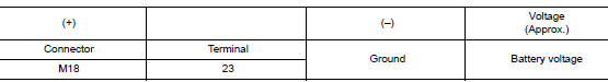
Is the inspection result normal? YES >> Replace the BCM. Refer to BCS-75, "Removal and Installation" (with Intelligent Key system) or BCS-135, "Removal and Installation" (without Intelligent Key system).
NO >> GO TO 2.
2. CHECK HARNESS CONTINUITY
- Turn ignition switch OFF.
- Disconnect BCM and power window relay.
- Check continuity between BCM connector and power window relay connector.
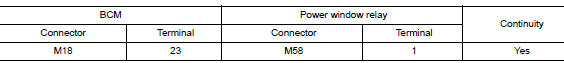
Is the inspection result normal? YES >> GO TO 3.
NO >> Repair or replace harness.
3. CHECK POWER WINDOW RELAY
Check power window relay.
Refer to PWC-49, "Component Inspection".
Is the inspection result normal? YES >> Check intermittent incident. Refer to GI-41, "Intermittent Incident".
NO >> Replace power window relay.
Component Inspection
1. CHECK POWER WINDOW RELAY
Check power window relay.
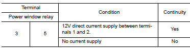
Is the inspection result normal? YES >> Inspection End.
NO >> Replace power window relay.
 Encoder circuit
Description
Detects condition of the front power window motor LH operation and transmits
to main power window and door
lock/unlock switch as pulse signal.
Component Function Check
1.CHECK ENCODE ...
 Door switch
WITH INTELLIGENT KEY
WITH INTELLIGENT KEY : Component Function Check
1.CHECK FUNCTION
Select "DOOR LOCK" of "BCM" using CONSULT.
Select "DOOR SW-DR", ...
Other materials:
Removal and installation
A/C SWITCH ASSEMBLY
Removal and Installation
REMOVAL
Release the A/C switch assembly clips and pawls using a suitable
tool.
: Metal clip
: Pawl
Disconnect the harness connector from the A/C switch assembly
(1) and remove.
INSTALLATION
Installation is in the reve ...
Engine coolant
Inspection
LEVEL
Check that the reservoir tank engine coolant level is within the
“MIN” to “MAX” when the engine is cool.
(A) : MAX
(B) : MIN
Adjust the engine coolant level if necessary.
CAUTION:
Refill Genuine NISSAN Long Life Antifreeze/Coolant (blue) or
equiva ...
Audible reminders
Brake pad wear warning
The disc brake pads have audible wear warnings.
When a disc brake pad requires replacement, it
makes a high pitched scraping sound when the
vehicle is in motion, whether or not the brake
pedal is depressed. Have the brakes checked as
soon as possible if the warning sou ...
