Nissan Rogue Service Manual: Encoder circuit
Description
Detects condition of the front power window motor LH operation and transmits to main power window and door lock/unlock switch as pulse signal.
Component Function Check
1.CHECK ENCODER OPERATION
Check front driver side door glass perform AUTO open/close operation normally when main power window and door lock/unlock switch.
Is the inspection result normal? YES >> Encoder operation is OK.
NO >> Refer to PWC-45, "Diagnosis Procedure"
Diagnosis Procedure
Encoder Circuit Check
1.CHECK ENCODER OPERATION
- Turn ignition switch ON.
- Check signal between main power window and door lock/unlock switch harness connector and ground with oscilloscope.
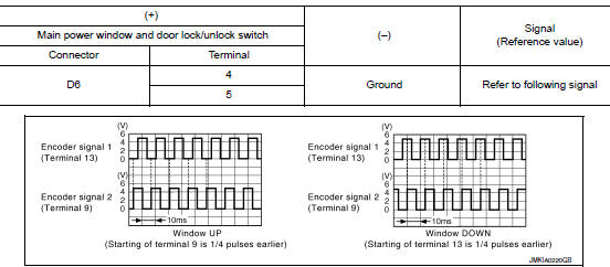
Is the inspection result normal? YES >> GO TO 7.
NO >> GO TO 2.
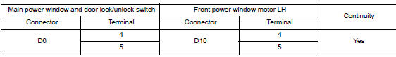
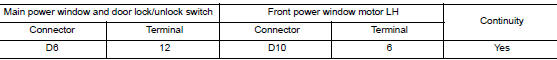
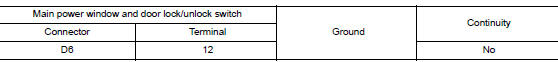
2.CHECK ENCORDER SIGNAL CIRCUIT
- Turn ignition switch OFF.
- Disconnect main power window and door lock/unlock switch connector and front power window motor LH connector.
- Check continuity between main power window and door lock/unlock switch harness connector and front power window motor LH harness connector.
- Check continuity between main power window and door lock/unlock switch harness connector and ground.
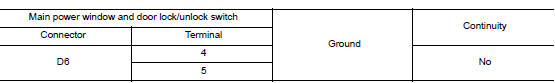
Is the inspection result normal? YES >> GO TO 3.
NO >> Repair or replace harness.
3.CHECK ENCORDER POWER SUPPLY CIRCUIT
- Connect main power window and door lock/unlock switch connector.
- Turn ignition switch ON.
- Check voltage between front power window motor LH harness connector and ground.
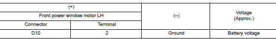
Is the inspection result normal? YES >> GO TO 4.
NO >> GO TO 5.
4.CHECK GROUND CIRCUIT
- Turn ignition switch OFF.
- Check continuity between front power window motor LH harness connector and ground.
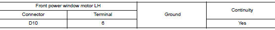
Is the inspection result normal? YES >> GO TO 7.
NO >> GO TO 6.
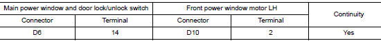
5.CHECK HARNESS CONTINUITY 1
- Turn ignition switch OFF.
- Check continuity between main power window and door lock/unlock switch harness connector and front power window motor LH harness connector.
- Check continuity between main power window and door lock/unlock switch harness connector and ground.
Is the inspection result normal? YES >> Replace main power window and door lock/unlock switch. Refer to PWC-65, "Removal and Installation".
NO >> Repair or replace harness.
6.CHECK HARNESS CONTINUITY 2
- Disconnect main power window and door lock/unlock switch connector.
- Check continuity between main power window and door lock/unlock switch harness connector and front power window motor LH harness connector.
Is the inspection result normal? YES >> Replace main power window and door lock/unlock switch. Refer to PWC-65, "Removal and Installation".
NO >> Repair or replace harness.
7.CHECK INTERMITTENT INCIDENT
Refer to GI-41, "Intermittent Incident".
>> Inspection End.
 Power window motor
DRIVER SIDE
DRIVER SIDE : Description
Door glass moves UP/DOWN by receiving the signal from main power window and
door lock/unlock switch.
DRIVER SIDE : Component Function Check
1. CHECK FRONT P ...
 Power window relay
Description
Power is supplied to the main power window and door lock/unlock with BCM
control.
Component Function Check
1. CHECK POWER WINDOW RELAY POWER SUPPLY CIRCUIT
Check that an operation no ...
Other materials:
Flexible seating
WARNING
Never allow anyone to ride in the cargo
area or on the rear seats when they are
in the fold-down position. In a collision,
people riding in these areas without
proper restraints are more likely to be
seriously injured or killed.
Do not allow peo ...
Inside mirror
Exploded View
MANUAL ANTI-DAZZLING
Windshield glass
Mirror base
Inside mirror
AUTO ANTI-DAZZLING
Windshield glass
Mirror base
Inside mirror
Inside mirror finisher
Harness connector
Bolt
Removal and Installation
MANUAL ANTI-DAZZLING
Removal ...
B0010, B0011 passenger airbag module
DTC Logic
DTC DETECTION LOGIC
CONSULT name
DTC
DTC detecting condition
Repair order
ASSIST AIRBAG MODULE CIRCUIT
[OPEN]
B0010
Front passenger air bag module circuit
(AS1) is open.
Refer to SRC-49, "Diagnosis Procedure".
ASS ...
