Nissan Rogue Service Manual: Power window motor
DRIVER SIDE
DRIVER SIDE : Description
Door glass moves UP/DOWN by receiving the signal from main power window and door lock/unlock switch.
DRIVER SIDE : Component Function Check
1. CHECK FRONT POWER WINDOW MOTOR LH OPERATION
Check front power window motor LH operation with main power window and door lock/unlock switch.
Is the inspection result normal? YES >> Front power window motor LH is OK.
NO >> Refer to PWC-38, "DRIVER SIDE : Diagnosis Procedure".
DRIVER SIDE : Diagnosis Procedure
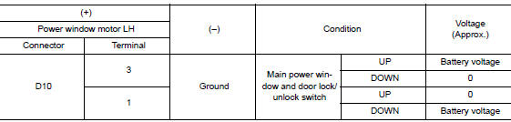
1.CHECK POWER WINDOW MOTOR LH INPUT SIGNAL
- Turn ignition switch OFF.
- Disconnect front power window motor LH connector.
- Turn ignition switch ON.
- Check voltage between power window motor LH harness connector and ground.
Is the inspection result normal? YES >> GO TO 3.
NO >> GO TO 2.
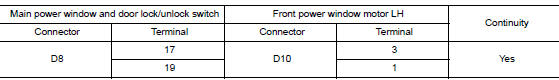
2.CHECK POWER WINDOW MOTOR CIRCUIT
- Turn ignition switch OFF.
- Disconnect main power window and door lock/unlock switch connector.
- Check continuity between main power window and door lock/unlock switch harness connector and front power window motor LH harness connector.
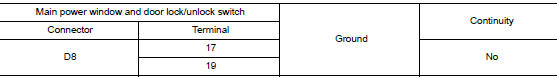
- Check continuity between main power window and door lock/unlock switch harness connector and ground.
Is the inspection result normal?
YES >> Replace main power window and door lock/unlock switch.Refer to PWC-64, "Removal and Installation".
NO >> Repair or replace harness.
3.CHECK FRONT POWER WINDOW MOTOR LH
Check front power window motor LH.
Refer to PWC-39, "DRIVER SIDE : Component Inspection".
Is the inspection result normal? YES >> GO TO 4.
NO >> Replace front power window motor LH. Refer to GW-16, "Removal and Installation".
4.CHECK INTERMITTENT INCIDENT
Refer to GI-41, "Intermittent Incident".
>> Inspection End.
DRIVER SIDE : Component Inspection
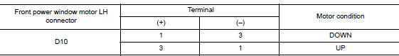
1.CHECK FRONT POWER WINDOW MOTOR LH
- Turn ignition switch OFF.
- Disconnect front power window motor LH connector.
- Check motor operate by connecting the battery voltage directly to front power window motor LH connector.
Is the inspection result normal? YES >> Inspection End.
NO >> Replace front power window motor LH. Refer to GW-16, "Removal and Installation".
PASSENGER SIDE
PASSENGER SIDE : Description
Door glass moves UP/DOWN by receiving the signal from main power window and door lock/unlock switch or front power window switch (passenger side).
PASSENGER SIDE : Component Function Check
1. CHECK FRONT POWER WINDOW MOTOR RH OPERATION
Check front power window motor RH operation with main power window and door lock/unlock switch or front power window switch RH.
Is the inspection result normal? YES >> Front power window motor RH is OK.
NO >> Refer to PWC-39, "PASSENGER SIDE : Diagnosis Procedure".
PASSENGER SIDE : Diagnosis Procedure
1.CHECK FRONT POWER WINDOW MOTOR RH INPUT SIGNAL
- Turn ignition switch OFF.
- Disconnect front power window motor RH connector.
- Turn ignition switch ON.
- Check voltage between front power window motor RH harness connector and groun
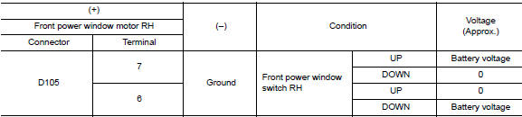
Is the inspection result normal? YES >> GO TO 3.
NO >> GO TO 2.
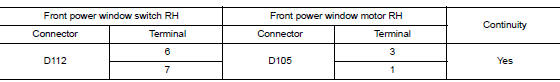
2.CHECK FRONT POWER WINDOW MOTOR RH CIRCUIT
- Turn ignition switch OFF.
- Disconnect front power window switch RH connector.
- Check continuity between front power window switch RH harness connector and front power window motor RH harness connector.
- Check continuity between front power window switch RH harness connector and ground.
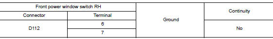
Is the inspection result normal? YES >> Replace front power window switch RH. Refer to PWC-65, "Removal and Installation".
NO >> Repair or replace harness.
3.CHECK FRONT POWER WINDOW MOTOR RH
Check front power window motor RH.
Refer to PWC-40, "PASSENGER SIDE : Component Inspection".
Is the inspection result normal? YES >> GO TO 4.
NO >> Replace front power window motor RH. Refer to GW-16, "Removal and Installation".
4.CHECK INTERMITTENT INCIDENT
Refer to GI-41, "Intermittent Incident".
>> Inspection End.
PASSENGER SIDE : Component Inspection
1.CHECK FRONT POWER WINDOW MOTOR RH
- Turn ignition switch OFF.
- Disconnect front power window motor RH connector.
- Check motor operate by connecting the battery voltage directly to front power window motor RH connector.
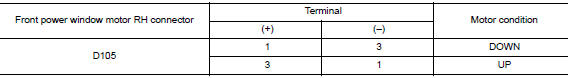
Is the inspection result normal? YES >> Inspection End.
NO >> Replace front power window motor RH. Refer to GW-16, "Removal and Installation".
REAR LH
REAR LH : Description
Door glass moves UP/DOWN by receiving the signal from main power window and door lock/unlock switch or rear power window switch LH.
REAR LH : Component Function Check
1.CHECK REAR POWER WINDOW MOTOR LH OPERATION
Check rear power window motor LH operation with main power window and door lock/unlock switch or rear power window switch LH.
Is the inspection result normal? YES >> Rear power window motor LH is OK.
NO >> Refer to PWC-41, "REAR LH : Diagnosis Procedure"
REAR LH : Diagnosis Procedure
1.CHECK REAR POWER WINDOW MOTOR LH INPUT SIGNAL
- Turn ignition switch OFF.
- Disconnect rear power window motor LH connector.
- Turn ignition switch ON.
- Check voltage between rear power window motor LH harness connector and ground
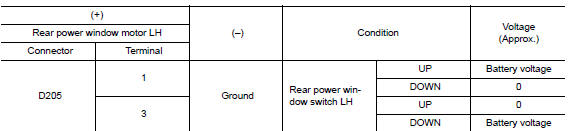
Is the inspection result normal? YES >> GO TO 3.
NO >> GO TO 2.
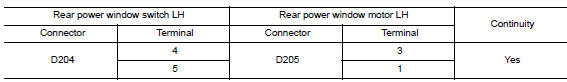
2.CHECK REAR POWER WINDOW MOTOR LH CIRCUIT
- Turn ignition switch OFF.
- Disconnect rear power window switch LH connector.
- Check continuity between rear power window switch LH harness connector and rear power window motor LH harness connector.
- Check continuity between rear power window switch LH connector and ground.
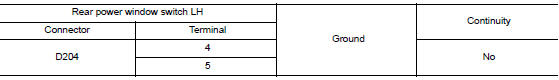
Is the inspection result normal? YES >> Replace rear power window switch LH.Refer to PWC-65, "Removal and Installation".
NO >> Repair or replace harness.
3.CHECK REAR POWER WINDOW MOTOR LH
Check rear power window motor LH.
Refer to PWC-42, "REAR LH : Component Inspection".
Is the inspection result normal? YES >> GO TO 4.
NO >> Replace rear power window motor LH. Refer to GW-22, "Removal and Installation".
4.CHECK INTERMITTENT INCIDENT
Refer to GI-41, "Intermittent Incident".
>> Inspection End.
REAR LH : Component Inspection
COMPONENT INSPECTION
1.CHECK REAR POWER WINDOW MOTOR LH
- Turn ignition switch OFF.
- Disconnect rear power window motor LH connector.
- Check motor operation by connecting the battery voltage directly to rear power window motor LH connector.
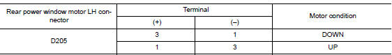
Is the inspection result normal? YES >> Inspection End.
NO >> Replace rear power window motor LH. Refer to GW-22, "Removal and Installation".
REAR RH
REAR RH : Description
Door glass moves UP/DOWN by receiving the signal from main power window and door lock/unlock switch or rear power window switch RH.
REAR RH : Component Function Check
1. CHECK REAR POWER WINDOW MOTOR RH OPERATION
Check rear power window motor RH operation with main power window and door lock/unlock switch or rear power window switch RH.
Is the inspection result normal? YES >> Rear power window motor RH is OK.
NO >> Refer to PWC-43, "REAR RH : Diagnosis Procedure".
REAR RH : Diagnosis Procedure
1.CHECK REAR POWER WINDOW MOTOR RH INPUT SIGNAL
- Turn ignition switch OFF.
- Disconnect rear power window motor RH connector.
- Turn ignition switch ON.
- Check voltage between rear power window motor RH harness connector and ground.
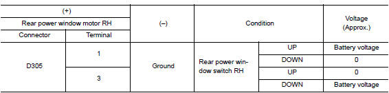
Is the inspection result normal? YES >> GO TO 3.
NO >> GO TO 2.
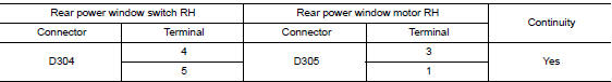
2.CHECK REAR POWER WINDOW MOTOR RH CIRCUIT
- Turn ignition switch OFF.
- Disconnect rear power window switch RH connector.
- Check continuity between rear power window switch RH harness connector and rear power window motor RH harness connector.
- Check continuity between rear power window switch RH harness connector and ground.
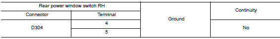
Is the inspection result normal? YES >> Replace rear power window switch RH.Refer to PWC-66, "Removal and Installation".
NO >> Repair or replace harness.
3.CHECK REAR POWER WINDOW MOTOR RH
Check rear power window motor RH.
Refer to PWC-44, "REAR RH : Component Inspection".
Is the inspection result normal? YES >> GO TO 4.
NO >> Replace rear power window motor RH. Refer to GW-22, "Removal and Installation".
4.CHECK INTERMITTENT INCIDENT
Refer to GI-41, "Intermittent Incident".
>> Inspection End.
REAR RH : Component Inspection
COMPONENT INSPECTION
1.CHECK REAR POWER WINDOW MOTOR RH
- Turn ignition switch OFF.
- Disconnect rear power window motor RH connector.
- Check motor operation by connecting the battery voltage directly to rear power window motor RH connector.
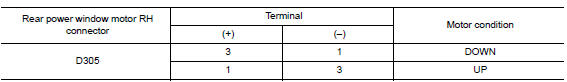
Is the inspection result normal? YES >> Inspection End.
NO >> Replace rear power window motor RH. Refer to GW-22, "Removal and Installation".
 Rear power window switch
Description
Rear power window motor will be operated if rear power window switch is
operated.
Component Function Check
1. CHECK REAR POWER WINDOW SWITCH FUNCTION
Check rear power window motor op ...
 Encoder circuit
Description
Detects condition of the front power window motor LH operation and transmits
to main power window and door
lock/unlock switch as pulse signal.
Component Function Check
1.CHECK ENCODE ...
Other materials:
Periodic maintenance
FRONT WHEEL HUB AND KNUCKLE
Inspection
Move the wheel hub and bearing in an axial direction by hand to verify
that looseness of wheel hub and
bearing exists. If any looseness exists, replace the wheel hub and bearing.
Axial end play : Refer to FAX-32, "Wheel Bearing".
Rota ...
Diagnosis system (BCM) (without intelligent key system)
COMMON ITEM
COMMON ITEM : CONSULT Function (BCM - COMMON ITEM)
APPLICATION ITEM
CONSULT performs the following functions via CAN communication with BCM.
Direct Diagnostic Mode
Description
Ecu Identification
The BCM part number is displayed.
Self Diagnostic ...
Precaution
Precaution for Supplemental Restraint System (SRS) "AIR BAG" and "SEAT
BELT
PRE-TENSIONER"
The Supplemental Restraint System such as “AIR BAG” and “SEAT BELT PRE-TENSIONER”,
used along
with a front seat belt, helps to reduce the risk or severity of injury to the
...
