Nissan Rogue Service Manual: Cylinder head
Exploded View
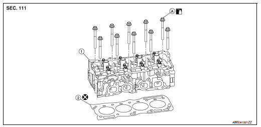
- Cylinder head
- Cylinder head gasket
- Refer to INSTALLATION
Removal and Installation
REMOVAL
- Remove the timing chain. Refer to EM-45, "Removal and Installation".
- Remove the camshafts. Refer to EM-64, "Exploded View".
- Remove spark plugs. Refer to EM-17, "Removal and Installation".
- Remove the intake manifold. Refer to EM-26, "Removal and Installation".
- Remove the exhaust manifold and three way catalyst. Refer to EM-29, "Removal and Installation".
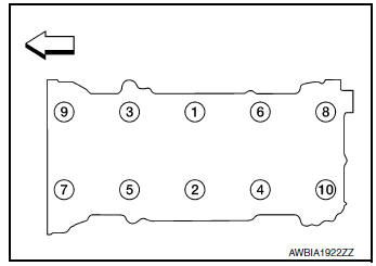
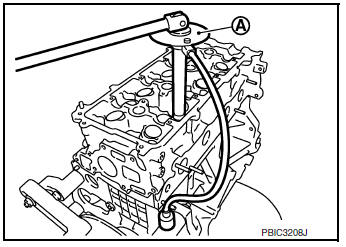
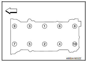
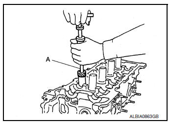
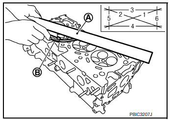
- Loosen the cylinder head bolts in the reverse order shown, using power tool.
 Engine front
- Remove cylinder head.
- Remove cylinder head gasket.
INSPECTION AFTER REMOVAL
Outer Diameter of Cylinder Head Bolts
- Replace the cylinder head bolts with new ones if the size difference between d1 and d2 exceeds the limit.
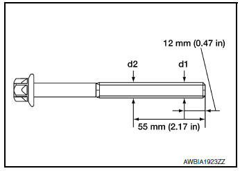
Limit (d1 - d2) : 0.23 mm (0.0091 in) or more
- If reduction of outer diameter appears in a position other than d2, use it as d2 point
INSTALLATION
- Clean surfaces of cylinder head and cylinder block.
- Install a new cylinder head gasket.
CAUTION: Do not reuse cylinder head gasket.
- Install the cylinder head.
- Follow the steps below to tighten the cylinder head bolts in the numerical order as shown.
- Clean threads and seating surfaces of bolts.
- Apply new engine oil to the threads and the seating surfaces of bolts.
CAUTION:
- If cylinder head bolts are re-used, check their outer diameters before installation. Follow the Outer Diameter of Cylinder Head Bolts measurement procedure.
- Check and confirm the tightening angle by using angle wrench or protractor. Do not judge angle by visual inspection.
Tool number (A) : KV10112100 (BT-8653-A)
Step a : 50 N·m (5.1 kg-m, 37 ft-lb) in order
Step b : 60° clockwise in order
Step c : Loosen to 0 N·m in order
Step d : 39.2 N·m (4.0 kg-m, 29 ft-lb) in order
Step e : 75° clockwise in order
Step f : 75° clockwise in order
 Engine front
- Installation of the remaining components is in the reverse order of removal.
Disassembly and Assembly
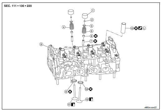
- Valve lifter
- Valve collet
- Valve spring retainer
- Valve spring (INT)
- Valve spring (EXH)
- Valve oil seal
- Valve guide
- Cylinder head
- Valve seat (INT)
- Valve seat (EXH)
- Valve (INT)
- Valve (EXH)
- Spark plug tube
- Apply thread locking sealant
CAUTION:
- When installing camshafts, chain tensioners, oil seals or other sliding parts, lubricate contacting surfaces with new engine oil.
- Apply new engine oil to threads and seat surfaces when installing the cylinder head, camshaft sprocket, crankshaft pulley and camshaft bracket.
- Attach tags to valve lifters so all parts are assembled in their original position.
CAUTION: Read PRECAUTION carefully.
The exhaust valve contains metallic sodium. Therefore, extreme caution must be taken when handling and disposing of the exhaust valve. Refer to EM-4, "Special Cautions to Ensure the Safe Disposal of Sodium-filled Exhaust Valves".
DISASSEMBLY
- Remove the valve lifter.
NOTE: Confirm installation point to return valve lifter to original location during assembly.
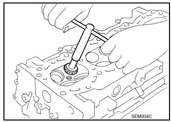
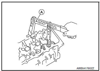
- Remove valve collet, valve spring retainer, and valve spring using suitable tool (A). Remove valve collet with magnetic hand.
CAUTION:
- Be careful not to damage valve lifter holes.
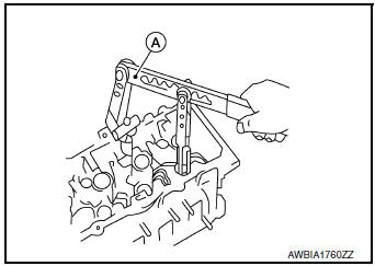
- Install suitable tool (A) in the center of valve spring retainer (1) to install it.
- Remove valve spring retainer and valve spring (with valve spring seat).
CAUTION: Do not remove valve spring seat from valve spring.
- Push valve stem to combustion chamber side, and remove valve.
- Inspect valve guide clearance before removal. Refer to EM-61, "Inspection After Disassembly".
- Confirm installation point to return valve to original location during assembly.
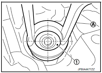
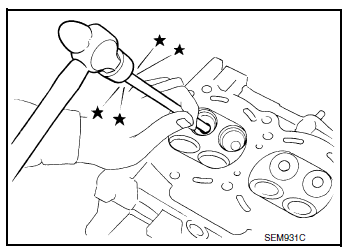
- Remove valve oil seal using suitable tool (A).
- Remove valve seat, if necessary.
- Bore out old seat until it collapses. Boring should not continue
beyond the bottom face of the seat
recess in cylinder head. Set the machine depth stop to ensure this. Refer to
EM-118, "Cylinder Head".
CAUTION: Do not bore excessively to prevent damage to cylinder head.
- Remove valve guide, if necessary
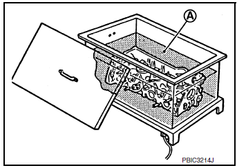
- To remove valve guide, heat cylinder head to 110°C to 130°C
(230°F to 266°F) by soaking in heated engine oil (A).
WARNING: Cylinder head contains heat. When working, wear protective equipment to avoid getting burned.
- Drive out valve guide using suitable tool.
- Remove spark plugs. Refer to EM-17, "Removal and Installation"
- Remove spark plug tubes, if necessary, using suitable tool.
CAUTION:
- Be careful not to damage cylinder head.
- Do not remove spark plug tube if not necessary. Once removed, the spark plug tube cannot be reused because of deformation during removal.
ASSEMBLY
- Install valve guide, if removed.
- Ream cylinder head valve guide hole using suitable tool (A).
Refer to EM-118, "Cylinder Head".
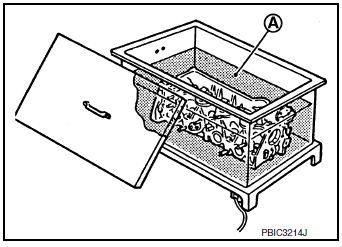
- Heat cylinder head to 110°C to 130°C (230°F to 266°F) by soaking
in heated engine oil (A).
WARNING: Cylinder head contains heat. When working, wear protective equipment to avoid getting burned.
- Press valve guide (1) into cylinder head (2) from camshaft side to dimension as shown.
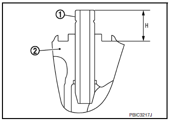
Projection (H) : Refer to EM-118, "Cylinder Head"
- Apply reamer finish to valve guide using suitable tool (A).
Standard : Refer to EM-118, "Cylinder Head"
- Install valve seat, if removed.
- Ream cylinder head (1) recess diameter for service valve seat (2).
- Heat cylinder head to 110°C to 130°C (230°F to 266°F) by soaking
in heated engine oil (A).
WARNING: Cylinder head contains heat. When working, wear protective equipment to avoid getting burned.
- Allow valve seats to cool with dry ice. Press-fit valve seat into
cylinder head.
CAUTION: Do not touch cold valve seats directly.
- Finish valve seat to the specified dimension using suitable tool.
Refer to EM-118, "Cylinder Head".
CAUTION: When using valve seat cutter, firmly grip the cutter handle with both hands. Then, press on the contacting surface all around the circumference to cut in a single drive. Improper pressure on the cutter or cutting many different times may result in stage valve seat.
- Using compound, grind to adjust valve.
- Check again for normal contact. Refer to EM-118, "Cylinder Head".
(A) : OK
(B) : NG
- Apply new engine oil to new valve oil seal joint surface and seal lip.
- Install new valve oil seal using suitable tool (A) as shown.
NOTE: Dimension is height measured before installing valve spring (with valve spring seat).
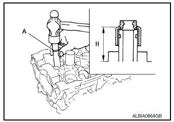
Projection (H) : Refer to EM-118, "Cylinder Head"
- Install valve.
- Install larger diameter to intake side.
- Install valve spring with valve spring seat (1).
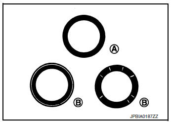
- Install valve spring so that the identification color faces upward (A).
- Install smaller pitch to cylinder head side (B).
- Confirm the identification color of the valve spring.
Intake : White
Exhaust : Light blue
- Install valve spring retainer.
- Install valve collet.
- Compress valve spring using suitable tool (A). Install valve collet
with a magnet hand.
CAUTION: When working do not damage valve lifter holes.
- Tap valve stem edge lightly with a plastic hammer after installation to check its installed condition.
- Install valve lifter.
- Install spark plug. Refer to EM-17, "Removal and Installation"
Inspection After Disassembly
CYLINDER HEAD DISTORTION
- Wipe off engine oil and remove water scale deposits, old gasket,
old sealer, and carbon using a suitable tool.
CAUTION: Use care not to allow gasket debris to enter passages for engine oil or engine coolant.
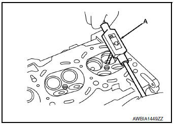
- At each of several locations on bottom surface of cylinder head, measure distortion in six directions using suitable tools (A, B).
Limit : Refer to EM-118, "Cylinder Head"
- If measurements exceed the limit, replace cylinder head.
VALVE DIMENSIONS
- Check dimensions of each valve. Refer to EM-118, "Cylinder Head".
- If dimensions are out of the standard, replace valve and check valve seat contact.
VALVE SEAT CONTACT
NOTE: After confirming that the dimensions of valve guides and valves are within specifications, perform this procedure:
- Apply prussian blue (or white lead) onto contacting surface of valve seat to check the condition of the vavle contact on the seat surface.
- Ensure that the contact area band is continuous all around the circumference.
(A) : OK
(B) : NG
- If the contact area is not continuous, grind to adjust valve fitting and check again. If the contacting surface still has NG conditions even after the re-check, replace the valve seat.
VALVE GUIDE CLEARANCE
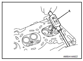
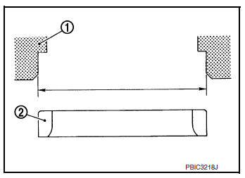
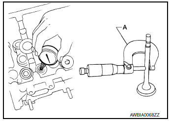
- Measure diameter of valve stem using suitable tool (A) as shown.
Standard : Refer to EM-118, "Cylinder Head"
- Measure inner diameter of valve guide using suitable tool.
Standard : Refer to EM-118, "Cylinder Head"
- Valve guide clearance = (Valve guide inner diameter) - (Valve stem diameter)
Standard and Limit : Refer to EM-118, "Cylinder Head"
- If the calculated value exceeds the limit, replace valve and/or valve guide. When valve guide must be replaced. Refer to EM-56, "Disassembly and Assembly"
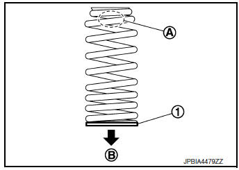
VALVE SPRING SQUARENESS
CAUTION: Do not remove the valve spring seat from the valve spring
- Set a try square (A) along the side of valve spring and rotate spring. Measure the maximum clearance between the top of spring and try square.
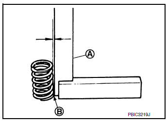
(B) : Contact
Limit : Refer to EM-118, "Cylinder Head".
- If the valve spring exceeds the limit, replace the valve spring with the valve spring seat.
VALVE SPRING PRESSURE LOAD
CAUTION: Do not remove the valve spring seat.
- Check valve spring pressure with valve spring seat installed at the specified spring height.
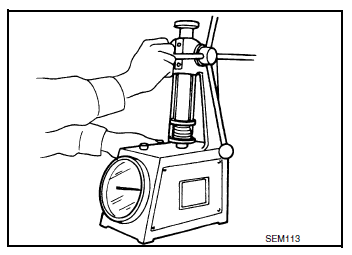
Standard : Refer to EM-118, "Cylinder Head".
- If the installation load or load with valve open is out of the standard, replace valve spring with valve spring seat.
INSPECTION AFTER INSTALLATION
Inspection for Leaks
- Before starting engine, check oil/fluid levels including engine coolant and engine oil. If less than required quantity, fill to the specified level. Refer to LU-8, "Refilling".
- Use the following steps to check for fuel leaks.
- Turn ignition switch "ON" (with engine stopped).
- With fuel pressure applied to fuel piping, check for fuel leaks at connection points.
- Start engine.
- With engine speed increased, check again for fuel leaks at connection points.
- Run engine to check for unusual noise and vibration.
NOTE: If hydraulic pressure inside timing chain tensioner drops after removal and installation, slack in the guide may generate a pounding noise during and just after engine start. However, this is normal. Noise will stop after hydraulic pressure rises.
- Warm up engine thoroughly to check there are no fuel leaks, exhaust gas leaks, or any oil/fluid leaks including engine oil and engine coolant.
- Bleed air from lines and hoses of applicable lines, such as in cooling system.
- After cooling down engine, again check oil/fluid levels including engine oil and engine coolant. Refill to the specified level, if necessary.
Summary of the inspection items:
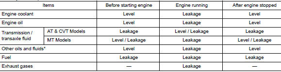
*: Power steering fluid, brake fluid, etc.
 Timing chain
Exploded View
Cylinder block
Timing chain slack guide
Chain tensioner
Timing chain
Camshaft sprocket (EXH)
Camshaft sprocket (INT)
Oil filte ...
 Camshaft
Exploded View
Camshaft position sensor (INT)
O-ring
Camshaft brackets (INT)
Camshaft brackets (EXH)
Camshaft (INT)
O-ring
Camshaft bracket (No. 1)
Camshaft sproc ...
Other materials:
FM/AM radio with compact disc (CD) player
(if so equipped)
FM/AM radio with compact disc (CD) player
CD eject button
CD button
Display screen
CD insert slot
SEEK button
SCAN button
TRACK button
BACK button
iPod MENU button
TUNE/FOLDER knob, ENTER/SETTING
button
Sta ...
Voice commands
Voice commands can be used to operate the
Bluetooth® Hands-Free Phone System. Press
the button and say “Phone” to
bring up the
phone command menu. The available options
are:
Call
Phonebook
Recent Calls
Messaging (if available)
Show Applications ( ...
Symptom diagnosis
COMBINATION SWITCH SYSTEM SYMPTOMS
Symptom Table
Perform the data monitor of CONSULT to check for any malfunctioning
item.
Check the malfunction combinations.
Identify the malfunctioning part from the agreed combination and repair
or replace the part.
NORMAL OPERA ...
