Nissan Rogue Service Manual: Timing chain
Exploded View
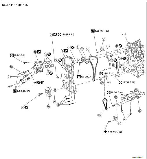
- Cylinder block
- Timing chain slack guide
- Chain tensioner
- Timing chain
- Camshaft sprocket (EXH)
- Camshaft sprocket (INT)
- Oil filter
- Front cover
- O-ring
- Oil pressure sensor
- Valve timing control cover O-rings
- Valve timing control cover
- Intake valve timing intermediate lock control solenoid valve
- Intake valve timing control solenoid valve
- Exhaust valve timing control solenoid valve
- Valve timing control solenoid valve Orings
- Valve timing control cover O-rings
- Front oil seal
- Crankshaft pulley
- Balancer unit timing chain
- Balancer unit timing chain tensioner
- Balancer unit
- Balancer unit sprocket
- Oil pump drive spacer
- Crankshaft sprocket
- Timing chain tension guide
- O-ring
- O-ring
- O-ring
- Refer to INSTALLATION
Removal and Installation
CAUTION: Apply new engine oil to parts as indicated in the illustration before installation.
REMOVAL
- Remove the engine and transaxle assembly. Refer to EM-81, "Exploded View".
- Remove intake manifold. Refer to EM-26, "Removal and Installation".
- Remove the drive plate assembly. Refer to EM-92, "Exploded View".
- Install engine to a suitable engine stand. Refer to EM-91, "Setting".
- Disconnect harness connector from intake valve timing intermediate lock control solenoid valve.
- Disconnect harness connector from intake valve timing control solenoid valve.
- Disconnect harness connector from exhaust valve timing control solenoid valve.
- Remove valve timing control cover.
- Remove the upper and lower oil pan, oil strainer, and O-ring. Refer to EM-32, "Removal and Installation".
- Remove generator. Refer to CHG-20, "Removal and Installation".
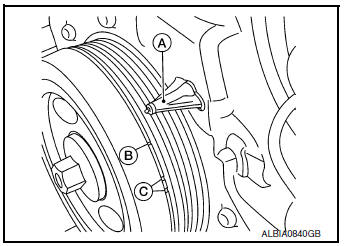
- Set the No.1 cylinder at TDC on the compression stroke using the following procedure:
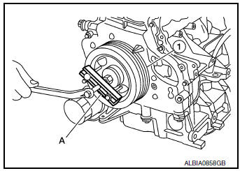
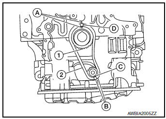
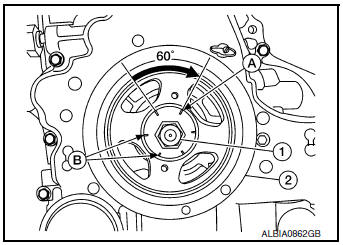
- Rotate the crankshaft pulley clockwise and align the mating
mark (B) to the timing indicator (A) on the front cover.
NOTE: Do not use the white paint marks (C).
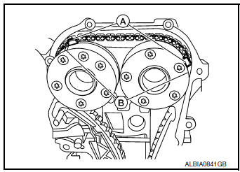
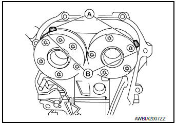
- At the same time, make sure that the camshaft sprocket mating marks (B) line up with the painted marks on the timing chain (A).
- If not lined up, rotate the crankshaft pulley one more turn to
line up the mating marks to the positions as shown.
NOTE: Shown with front cover removed for illustration purposes only.
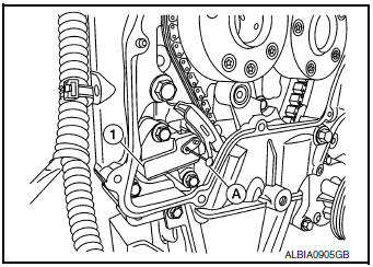
- Remove crankshaft pulley (1) using the following procedure:
- Hold the crankshaft pulley (1) using suitable tool (A), then loosen and remove the crankshaft pulley bolt.
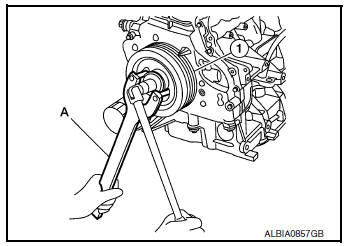
- Attach suitable tool (A) in the M 6 (0.24 in diameter) thread hole on crankshaft pulley (1), and remove crankshaft pulley.
- Remove the intake valve timing control cover. Refer to EM-75, "Valve Timing Control Cover".
- Remove the front cover using the following procedure:
- Loosen the bolts in reverse order as shown, and remove them.
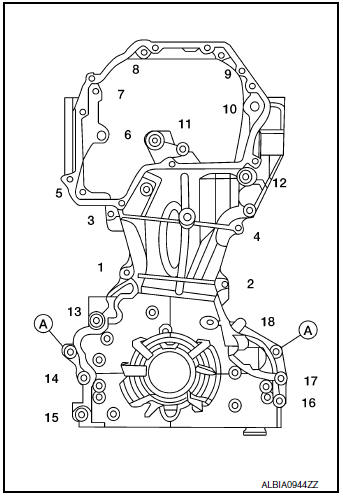
(A) : Dowel pin
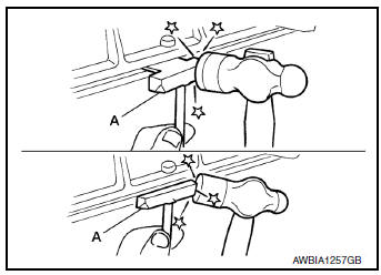
- Cut liquid gasket using Tool (A).
Tool number : KV10111100 (J-37228)
CAUTION: Be careful not to damage the front cover.
- Remove the front cover.
- Remove front oil seal using suitable tool, (if necessary).
CAUTION: Be careful not to damage the front cover.
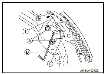
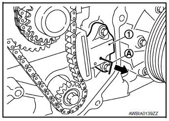
- Remove chain tensioner (1) and timing chain using the following procedure:
- Pull the lever (B) down and release the plunger stopper tab (C).
- Plunger stopper tab (C) can be pushed up to release (coaxial structure with lever (B)).
- Insert the stopper pin (A) into the tensioner body hole to hold
the
lever (B) and keep tab released.
NOTE: Allen wrench [2.5 mm (0.098)] is used for a stopper pin as an example.
- Insert plunger (C) into tensioner body by pressing timing chain slack guide (1).
- Keep timing chain slack (1) guide pressed and hold it by pushing the stopper pin (B) through the lever hole and body hole.
- Remove the chain tensioner bolts (A) and chain tensioner.
- Remove the timing chain.
CAUTION: Do not rotate the crankshaft or camshafts while the timing chain is removed. It can cause damage to the valves and pistons.
- Remove the camshaft sprockets using the following procedure:
- Secure hexagonal part of the camshaft with a wrench and loosen the camshaft sprocket bolt.
- Remove the camshaft sprocket bolt and camshaft sprockets for both camshafts.
- Remove the timing chain slack guide, timing chain tension guide, and oil pump drive spacer.
- Press stopper tab (A) in the direction shown to push the timing chain slack guide (B) toward timing chain tensioner (1) for the balancer unit.
- The timing chain slack guide (B) is released by pressing the stopper tab (A). As a result, the timing chain slack guide (B) can be moved.
- Insert stopper pin (D) into tensioner body hole (C) to secure
timing
chain slack guide (B).
NOTE: Use a hard metal pin with a diameter of approximately 1.2 mm (0.047 in) as a stopper pin.
- Remove timing chain tensioner (1) for balancer unit.
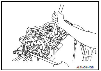
- Secure width across flats of the balancer unit LH side shaft
using a suitable tool. Loosen the balancer unit sprocket bolt.
22. Remove balancer unit timing chain, balancer unit sprocket and crankshaft sprocket.
- Loosen bolts in the reverse order shown, and remove balancer unit.
CAUTION:
- Do not disassemble balancer unit.
 Engine fron
INSPECTION AFTER REMOVAL
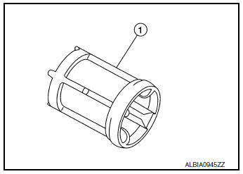
Oil Filter
- Check that there is no foreign material on the oil filter (1) and check for clogging.
- Check the oil filter for damage.
- If there is damage, replace the oil filter.
- Do not reuse oil filter.
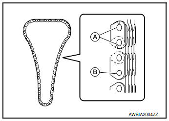
Timing Chain
Check the timing chain for cracks (A) or excessive wear (B). If a defect is found, replace the timing chain.
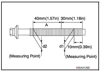
Balancer Unit Bolt Outer Diameter
- Measure outer diameters (d1, d2) at the two positions as shown.
- Measure d2 within the range (A).
- If the value difference (d1 - d2) exceeds the limit, replace the balancer unit bolt with a new one.
Limit : 0.15 mm (0. 0059 in) or more
INSTALLATION
- Make sure the crankshaft key points straight up.
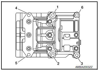
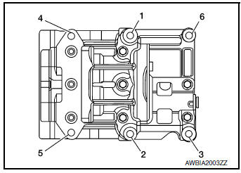
- Install the balancer unit and tighten the bolts in the numerical order as shown:
 Engine front
CAUTION:
- When reusing a bolt, check its outer diameter before installation. Follow the Balancer Unit Bolt Outer Diameter procedure.
- Apply new engine oil to threads and seating surfaces of bolts.
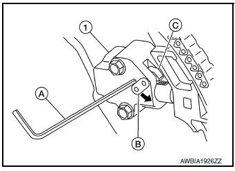
- Check tightening angle with an angle wrench (A) or a protractor.
Do not make judgment by visual check alone.
Tool number : KV10112100 (BT-8653-A)
Step 1
Bolts 1-5 : 42 N·m (4.3 kg-m, 31 ft-lb)
Bolt 6 : 36 N·m (3.7 kg-m, 27 ft-lb)
Step 2
Bolts 1-5 : 120° + 5°
Bolt 6 : 90° + 5°
Step 3
Loosen in reverse
order
: 0 N·m (0 kg-m, 0 ft-lb)
Step 4
Bolts 1-5 : 42 N·m (4.3 kg-m, 31 ft-lb)
Bolt 6 : 36 N·m (3.7 kg-m, 27 ft-lb)
Step 5
Bolts 1-5 : 120° + 5°
Bolt 6 : 90° + 5°
- Install the crankshaft sprocket (1) and timing chain (2) for the balancer unit.
- Make sure that the crankshaft sprocket (1) is positioned with mating marks (A) on the block and sprocket meeting at the top.
- Install it by lining up mating marks on each sprocket (A), (C) and timing chain (B), (D).
- (B): Pink link
- (D): Yellow link
- Install timing chain tensioner for balancer unit (1).
- Compress the plunger, insert a stopper pin (A), and then install the tensioner for the balancer unit.
- Do not pull out (
 )
the stopper pin until after installing the timing
chain tensioner for balancer unit.
)
the stopper pin until after installing the timing
chain tensioner for balancer unit. - Check matching mark position of balancer unit drive chain and each sprocket again.
- Install camshaft sprockets.
- Install them by lining up the mating marks on each camshaft sprocket (B) with the ones painted on the timing chain (A) during removal.
- Before installation of chain tensioner, it is possible to re-match the marks on timing chain with the ones on each sprocket.
CAUTION:
- Aligned mating marks could slip. Therefore, after matching them, hold the timing chain in place by hand.
- Before and after installing chain tensioner, check again to make sure that mating marks have not slipped.
- Install chain tensioner using the following procedure:
- Install stopper pin (A) into the chain tensioner (1).
- Install the chain tensioner and pull the stopper pin out.
CAUTION: After installation, pull the stopper pin out, and make sure that the tensioner is fully released.
- Install timing chain (1) and related parts.
- Install by lining up mating marks on each sprocket and timing chain as shown.
- Before and after installing chain tensioner (3), check to make sure the mating marks have not slipped.
- After installing timing chain tensioner (3), remove the stopper pin, and make sure that the tensioner moves freely.
CAUTION:
- For the following note, after the mating marks are aligned, keep them aligned by holding them by hand.
- To avoid skipped teeth, do not move crankshaft and camshaft until front cover is installed.
NOTE:
- Before installing chain tensioner (3) it is possible to slip the chain on the sprocket to align the chain timing mark with the sprocket timing mark.
- There may be two color variations of the link marks (link colors) on the timing chain.
- There are 26 links between the pink mating marks on the timing chain; and 64 links between the camshaft sprocket pink link and the crankshaft sprocket yellow link, on the timing chain side without the tensioner.
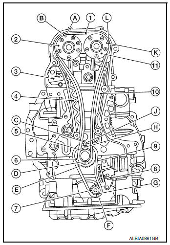
(2) : Camshaft sprocket (INT)
(4) : Timing chain slack guide
(5) : Crankshaft key
(6) : Crankshaft sprocket
(7) : Balancer unit sprocket
(8) : Balancer unit chain tensioner
(9) : Balancer unit timing chain
(10) : Timing chain tension guide
(11) : Camshaft sprocket (EXH)
(A) : Mating mark (Outer groove)
(B) : Pink link
(C) : Mating mark (lug)
(D) : Mating mark (stamp)
(E) : Yellow link
(F) : Pink link
(G) : Mating mark (stamp)
(H) : Mating mark (stamp)
(J) : Yellow link
(K) : Mating mark (Outer groove)
(L) : Pink link
- Install new front oil seal to front cover. Refer to EM-78, "FRONT OIL SEAL : Removal and Installation".
- Install front cover with the following procedure:
- Install O-rings to cylinder head and cylinder block.
CAUTION: Do not reuse O-rings.
- Apply a continuous bead of liquid gasket to front cover as shown.
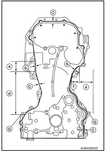
(a) : 35.7 mm (1.406 in)
(b) : 6.0 – 7.0 mm (0.236 – 0.276 in)
(c) : 3.4 – 4.4 mm (0.134 – 0.173 in)
(d) : 179.6 mm (7.07 in)
(e) : 35.5 mm (1.398 in)
(f) : 31.3 mm (1.232 in)
(G) : Dowel pin hole
Use Genuine RTV Silicone Sealant or equivalent. Refer to GI-22, "Recommended Chemical Products and Sealants".
CAUTION:
- Be sure sealant surfaces are free from grease, dirt, water, and engine oil.
- Be sure to apply sealant without breaks or overlap.
- Installation should be done within 5 minutes after application of liquid gasket.
- Do not fill the engine with engine oil for at least 30 minutes after the components are installed to allow the liquid gasket to cure.
- Make sure the mating marks on the timing chain and each sprocket are
still aligned. Then install the front
cover.
CAUTION: Do not damage the front oil seal during installation.
- Tighten front cover bolts in the numerical order shown.
- After all bolts are tightened, retighten them to the specified torque.
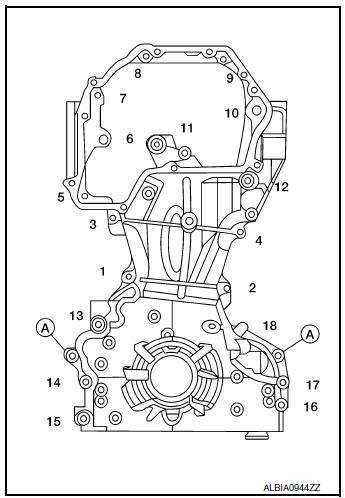
Front cover bolts
Bolts 6, 10, 12 : 49 N·m (5.0 kg-m, 36 ft-lb)
Bolts (all remaining) : 12.8 N·m (1.3 kg-m, 9 ft-lb)
(A) : Dowel pin
CAUTION: Wipe off excess sealant leaking at the surface for installing the oil pan.
- Install the chain guide between the camshaft sprockets.
- Install valve timing control cover. Refer to EM-75, "Valve Timing Control Cover".
- Insert crankshaft pulley by aligning with crankshaft key.
- Tap its center with a plastic hammer to insert.
CAUTION:
- Do not hit belt mounting section with hammer to avoid breaking belt guide.
- Be sure not to damage front oil seal while installing crankshaft pulley.
- Install crankshaft pulley bolt (1) and tighten to specification.
CAUTION:
- Apply anti-corrosive engine oil to threads of crankshaft pulley bolt (1) and bolt bearing surface prior to installation.
- Secure crankshaft pulley (2) with suitable tool to tighten the bolt.
Step 1 : Crankshaft bolt (1) : 42.1 N·m (4.3 kg-m,
31 ft-lb)
Step 2 : Crankshaft bolt (1) : 60° + 6°
- Apply a paint mark (A) on the front cover, mating with any one of six easy to recognize stamp marks on bolt flange (B).
- Installation of the remaining components is in the reverse order of removal.
 Fuel injector and fuel tube
Exploded View
Rocker cover
Cylinder head
Fuel tube
Clip
O-ring (green)
Fuel injector
O-ring (black)
Front
Removal and Installation
WARNING:
& ...
 Cylinder head
Exploded View
Cylinder head
Cylinder head gasket
Refer to INSTALLATION
Removal and Installation
REMOVAL
Remove the timing chain. Refer to EM-45, "Removal and ...
Other materials:
Removal and installation
A/C SWITCH ASSEMBLY
Removal and Installation
REMOVAL
Release the A/C switch assembly clips and pawls using a suitable
tool.
: Metal clip
: Pawl
Disconnect the harness connector from the A/C switch assembly
(1) and remove.
INSTALLATION
Installation is in the reve ...
Water hose
Exploded View
Water outlet
Hose clamp
Water hose A
Clip
CVT oil warmer
Transaxle assembly
Water hose B
Heater thermostat
Water hose C
: Always replace after every
disassembly.
: N·m (kg-m, ft-lb)
Removal and Installation
REMOVAL
WARNING:
Do not remove the rad ...
Circuit inspection
DESCRIPTION
In general, testing electrical circuits is an easy task if it is
approached in a logical and organized method.
Before beginning it is important to have all available information on the
system to be tested. Also, get a thorough
understanding of system operation. Then y ...
