Nissan Rogue Service Manual: Unit removal and installation
REAR FINAL DRIVE ASSEMBLY
Exploded View
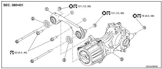
- Final drive mounting bracket
- Mounting stopper
- Rear final drive assembly
 : N·m (kg-m, ft-lb)
 : Always replace after every
disassembly.
: Always replace after every
disassembly.
Removal and Installation
REMOVAL
- Remove rear propeller shaft. Refer to DLN-99, "Exploded View".
- Remove rear drive shafts. Refer to RAX-19, "Exploded View".
- Disconnect AWD solenoid harness connector.
- Remove rear final drive breather hose and electric controlled coupling breather hose.
- Support final drive assembly with a suitable jack.
- Remove final drive nuts and final drive bolts with power tool.
If necessary, remove final drive bracket and washer with power tool.
CAUTION: Secure final drive assembly to a suitable jack while removing it.
INSTALLATION Installation is in the reverse order of removal.
- When oil leaks while removing final drive assembly, check oil level after the installation. Refer to DLN-111, "Inspection".
- When replacing rear final drive assembly, perform writing unit characteristics. Refer to DLN-35, "Work Procedure".
 Removal and installation
DRIVE PINION OIL SEAL
Exploded View
Rear final drive assembly
Drive pinion oil seal
Electric controlled coupling assembly
Oil seal lip
Always replace after every
disassembly.
: ...
 Unit disassembly and assembly
ELECTRIC CONTROLLED COUPLING
Exploded View
Stud bolt
Connector bracket
Reamer bolt
Electric controlled coupling assembly
Wave spring
Drive pinion oil seal
Drive pinion lock nut ...
Other materials:
B1431 seat belt pre-tensioner
DTC Logic
DTC DETECTION LOGIC
CONSULT name
DTC
DTC detecting condition
Repair order
FRONT PRE-TEN RH CIRCUIT
[OPEN]
B1431
RH seat belt pre-tensioner circuit is open.
Refer to SRC-61, "Diagnosis Procedure"
FRONT PRE-TEN RH CIRC ...
P0112, P0113 IAT sensor
DTC Description
DTC DETECTION LOGIC
DTC No.
CONSULT screen terms
(Trouble diagnosis content)
DTC detecting condition
P0112
IAT SEN/CIRCUIT- B1
(Intake air temperature sensor 1 circuit low
bank 1)
An excessively low voltage from the intake air temperature sensor ...
P0128 thermostat function
DTC Description
DTC DETECTION LOGIC
Engine coolant temperature has not risen enough to open the thermostat even
though the engine has run long
enough.
This is due to a leak in the seal or the thermostat being stuck open.
DTC No.
CONSULT screen terms
(Trouble diagnosis content)
...
