Nissan Rogue (T33) 2021-Present Service Manual: Type a :: Basic Inspection
Meter, Warning Lamp & Indicator
Diagnosis and Repair Workflow
Work flow
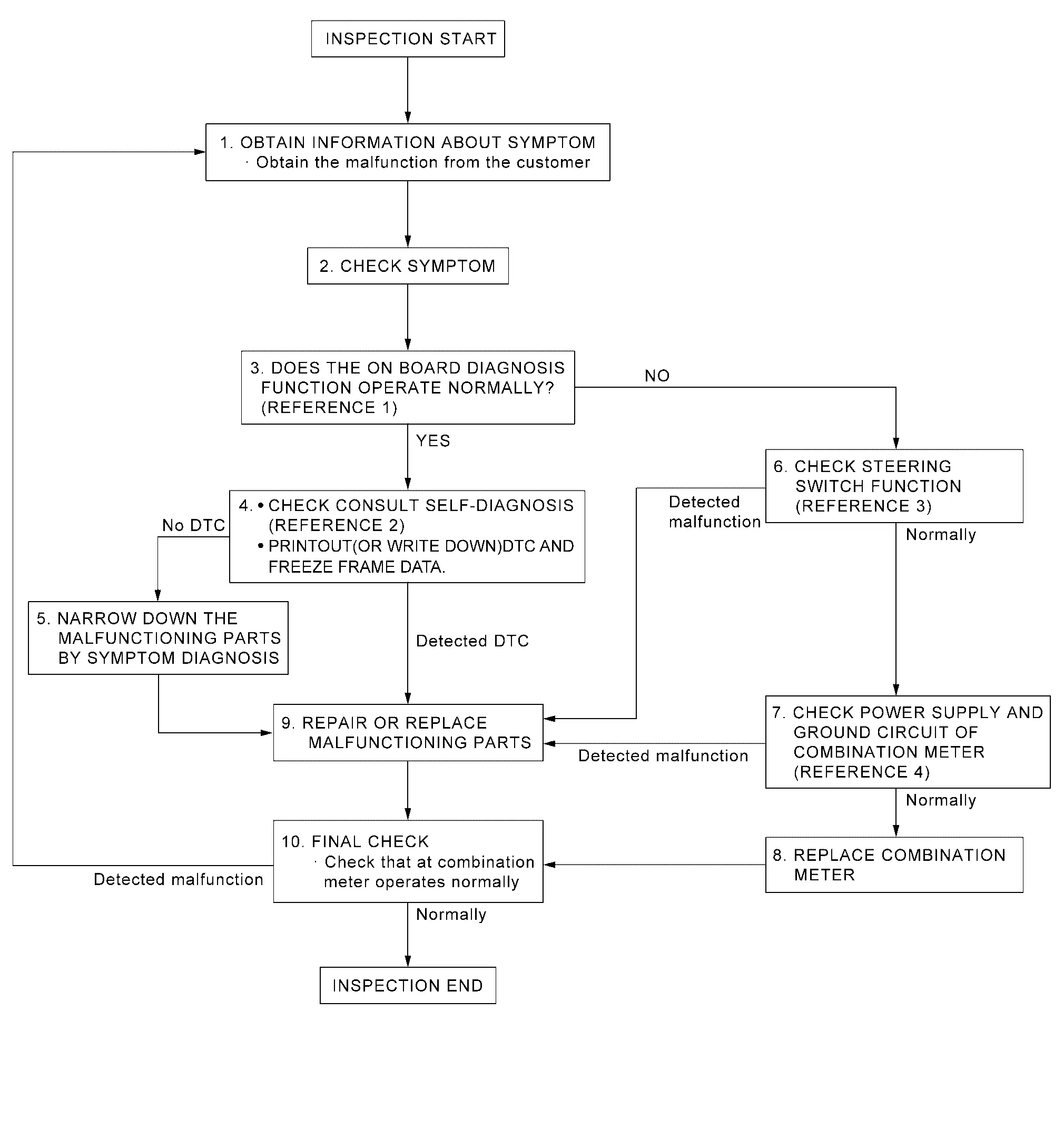
OVERALL SEQUENCE
-
Reference 1ôñôñôñOn Board Diagnosis Function.
-
Reference 2ôñôñôñDTC Index.
-
Reference 3ôñôñôñComponent Function Check.
-
Reference 4ôñôñôñDiagnosis Procedure.
DETAILED FLOW
OBTAIN INFORMATION ABOUT SYMPTOM
Interview the customer to obtain as much information as possible about the conditions and environment under which the malfunction occurred.
>>
GO TO 2.
CHECK SYMPTOM
-
Check the symptom based on the information obtained from the customer.
-
Check that any other malfunctions are present.
>>
GO TO 3.
CHECK ON BOARD DIAGNOSIS OPERATION
Check that the on board diagnosis function operates. Refer to On Board Diagnosis Function.
Does the on board diagnosis function operate normally?
YES>>GO TO 4.
NO>>GO TO 6.
CHECK CONSULT SELF-DIAGNOSIS RESULTS
 CONSULT
-
Perform self-diagnosis. Refer to DTC Index.
-
When DTC is detected, follow the instructions below:
-
Record DTC and Freeze Frame Data.
-
Are self-diagnosis results normal?
YES>>GO TO 5.
NO>>GO TO 9.
NARROW DOWN THE MALFUNCTIONING PARTS BY SYMPTOM DIAGNOSIS
Perform symptom diagnosis and narrow down the malfunctioning parts.
>>
GO TO 9.
CHECK STEERING SWITCH FUNCTION
Check steering switch function. Refer to Component Function Check.
Is inspection result normal?
YES>>GO TO 7.
NO>>GO TO 9.
CHECK COMBINATION METER POWER SUPPLY AND GROUND CIRCUITS
Check combination meter power supply and ground circuits. Refer to Diagnosis Procedure.
Is inspection result normal?
YES>>GO TO 8.
NO>>GO TO 9.
REPLACE COMBINATION METER
Replace combination meter.
>>
GO TO 10
REPAIR OR REPLACE MALFUNCTIONING PARTS
Repair or replace the malfunctioning parts.
 NOTE:
NOTE:
If DTC is displayed, erase DTC after repair or replace malfunctioning parts.
>>
GO TO 10.
FINAL CHECK
Check that the combination meter operates normally.
Do they operate normally?
YES>>Inspection End.
NO>>GO TO 1.
Additional Service When Replacing Combination Meter
Work Procedure
DESCRIPTION
When replacing the Combination meter, perform the procedures before and after replacement.
Before Replacement
Take note the odometer mileage of the combination meter. When replacing the combination meter, check that DTCãs are not detected at ãSelf diagnosis resultã of ABS. When detecting DTCãs, perform ãSelf diagnosis resultã of ABS.
After Replacement
After replacing the combination meter, the following items must be performed.
-
Configuration
-
Actual driving 0.6 mi (1 km) or more
NOTE:
The odometer mileage of the combination meter is also stored and memorized in the ABS actuator and electric unit (control unit). When driving 0.6 mi (1 km) or more after replacement of the combination meter, the memorized mileage in the ABS actuator and electric unit (control unit) is writed into the new combination meter.
WORK PROCEDURE
COMBINATION METER CONFIGURATION
CONSULT
Perform the combination meter configuration. Refer to Work Procedure.
>>
GO TO 2.
PERFORM SELF-DIAGNOSIS
CONSULT
Select ãSelf diagnosis resultã of combination meter. Check if any DTC is detected.
Is any DTC detected?
YES>>Perform the trouble diagnosis for the detected DTC. Refer to DTC Index.
NO>>GO TO 3.
DRIVING TEST
Drive the Nissan Ariya vehicle on the road 0.6 mi (1 km) or more.
Check that the odometer shows more than the mileage taken note before.
>>Inspection End.
Configuration (combination Meter)
Description
Vehicle specification needs to be written with CONSULT because it is not written after replacing the combination meter.
The configuration requires network connection. CONSULT connects to network and then it downloads the configuration data from the server. Then CONSULT writes the Nissan Ariya vehicle specification to the combination meter.
Refer to Work Procedure.
NOTE:
For details the network connection and operation, refer to ãCONSULT Operation Manualã.
The configuration no need to ãsaveã configuration data from the combination meter. The configuration data is always generated freshly at the server and then downloaded to the CONSULT.
CAUTION:
-
Complete the procedure of ãConfigurationã in order.
-
If incorrect ãConfigurationã, incidents might occur.
-
Never perform ãConfigurationã except for new combination meter.
Work Procedure
WRITING VEHICLE SPECIFICATION
CONSULT
Perform writing Nissan Ariya vehicle specification to combination meter following "Automatic Configuration" procedure of "Configuration" according to CONSULT Operation Manual.
NOTE:
-
Log in the network according to CONSULT guidance.
-
For details the network connection and operation, refer to ãCONSULT Operation Manualã.
>>
Work End.
Head up Display
Diagnosis and Repair Work Flow
Work Flow
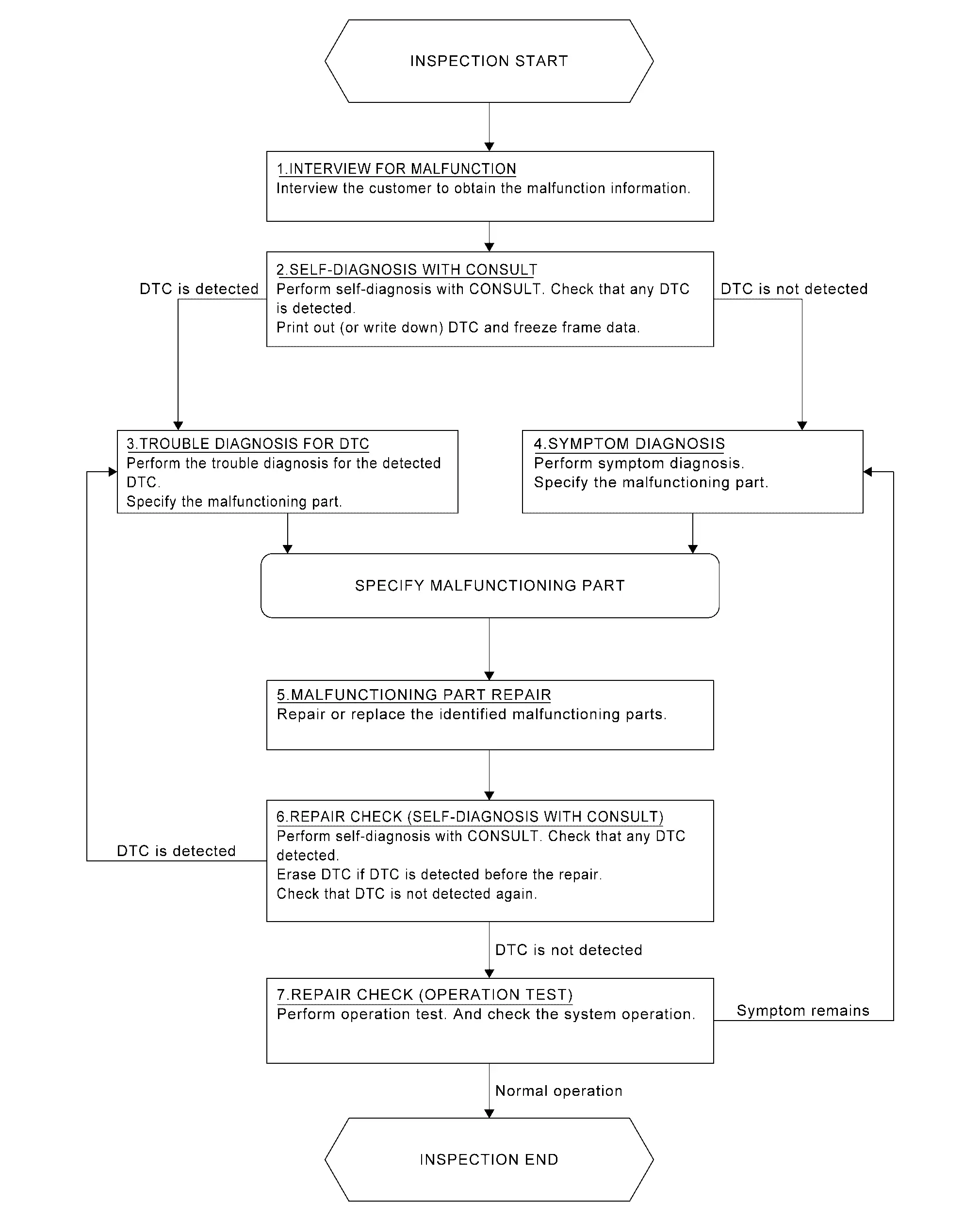
OVERALL SEQUENCE
DETAILED FLOW
INTERVIEW FOR MALFUNCTION
It is also important to clarify the customer concerns before starting the inspection. Interview the customer about the concerns carefully and understand the symptoms fully.
NOTE:
The customers are not professionals. Never assume that ãmaybe the customer meansôñôñôñã or ãmaybe the customer mentioned this symptomã.
>>
GO TO 2.
SELF-DIAGNOSIS
CONSULT
Perform self-diagnosis of ãHEAD UP DISPLAYã. Refer to CONSULT Function.
NOTE:
Skip to step 4 of the diagnosis procedure if ãHEAD UP DISPLAYã is not displayed.
Is any DTC detected?
YES>>GO TO 3.
NO>>GO TO 4.
TROUBLE DIAGNOSIS FOR DTC
-
Check the DTC indicated in the ãSelf diagnosis resultã.
-
When DTC is detected, follow the instructions below:
-
Record DTC
-
Freeze Frame Data (FFD)
-
-
Perform the relevant diagnosis referring to the DTC Index. Refer to DTC Index.
>>
GO TO 5.
SYMPTOM DIAGNOSIS
Perform the applicable diagnosis according to the diagnosis chart by symptom. Refer to Symptom Table.
>>
GO TO 5.
MALFUNCTIONING PART REPAIR
Repair or replace the identified malfunctioning parts.
>>
GO TO 6.
REPAIR CHECK (SELF-DIAGNOSIS)
CONSULT
-
Erases self-diagnosis results.
-
Perform self-diagnosis of ãHEAD UP DISPLAYã again after repairing or replacing the specific items.
-
Check if any DTC is detected in self-diagnosis results of ãHEAD UP DISPLAYã.
Is any DTC detected?
YES>>GO TO 3.
NO>>GO TO 7.
REPAIR CHECK (OPERATION TEST)
Perform operation test. Check that the malfunction symptom is solved or no other symptoms occur.
Is there a malfunction symptom?
YES>>GO TO 4.
NO>>Inspection End.
Additional Service When Replacing Head up Display Unit
Work Procedure
Description
When replacing or removing the Head Up Display unit, distortion calibration of the display and adjustment of the display position are required.
Work Procedure
REPLACE HEAD UP DISPLAY UNIT
Replace Head Up Display unit. Refer to Removal and Installation.
>>
GO TO 2.
PERFORM CALIBRATION
Perform Head Up Display calibration. Refer to Work Procedure.
>>
GO TO 3.
ADJUST DISPLAY SCREEN
Adjust display screen position. Refer to Switch Name and Function.
>>
GO TO 4.
OPERATION CHECK
Check the display of Head Up Display.
Is the displayed normal?
YES>>WORK END
NO>>Perform display adjustment again. GO TO 3.
Head up Display Calibration
Work Procedure
Description
Calibration must be performed after replacing or removing/installing the following parts:
-
Head Up Display unit
-
Windshield glass
-
Steering member
Diagnosis Procedure
NOTE:
-
Place the vehicle on level ground.
-
Keep the space when calibration. (Nissan Ariya Vehicle front area)
-
Wide: 2.0 m (6.56 ft)
-
Height: 2.0 m (6.56 ft)
-
Length: 2.0 m (6.56 ft)
-
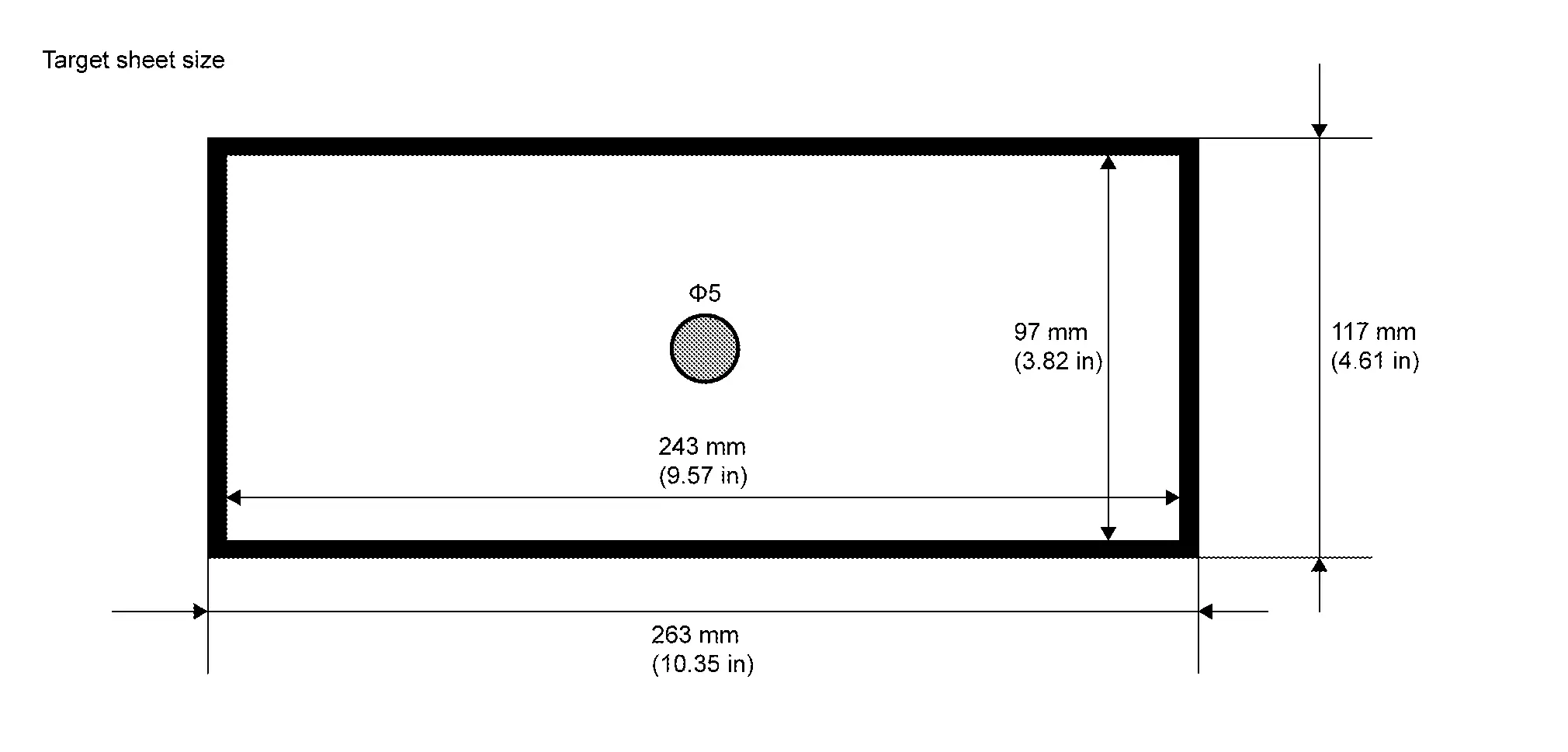
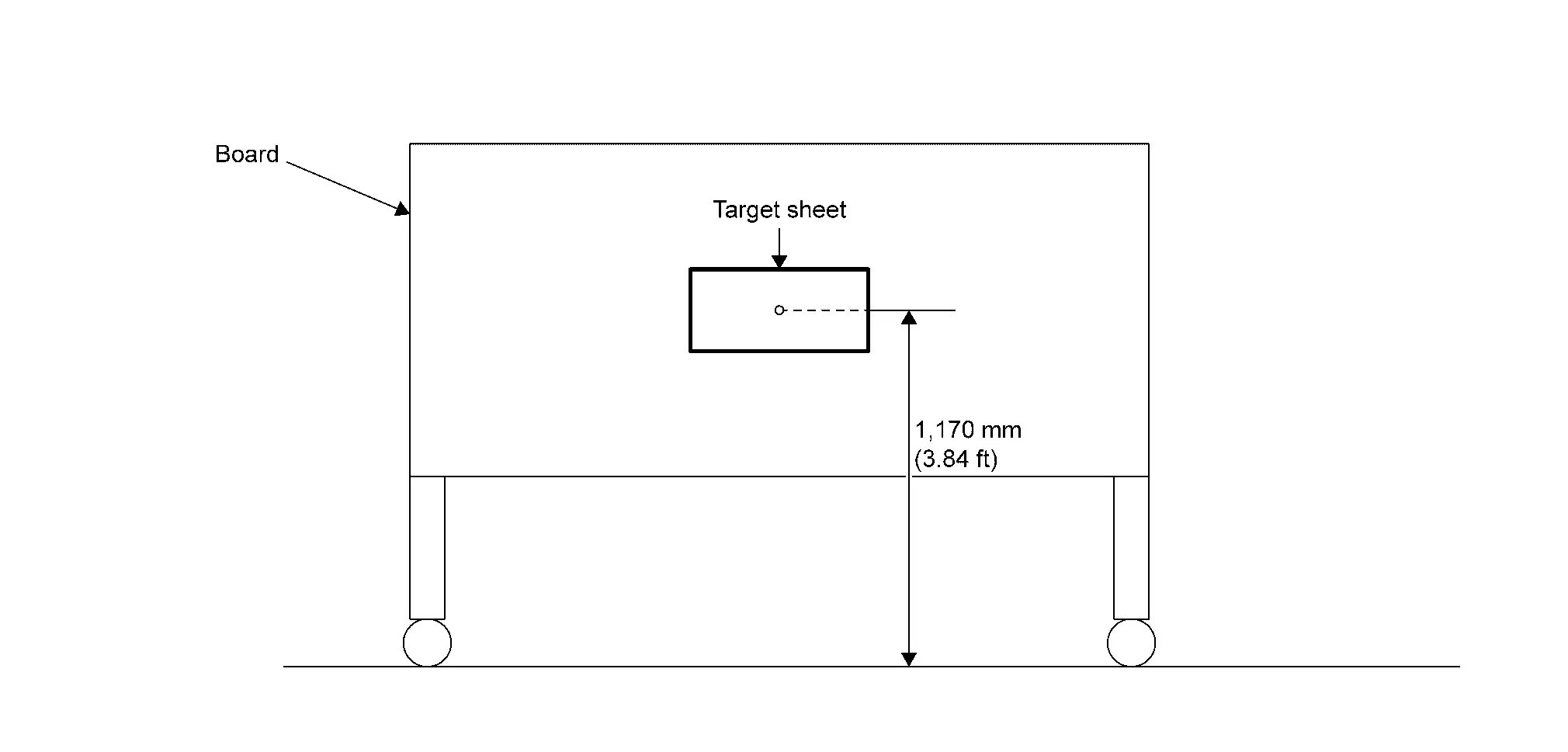
TARGET PREPARATION
Prepare the distortion calibration jig according to the following procedure and the figure.
-
Prepare target sheet according to the figure.
-
Paste the created target sheet onto the board according to the figure.
>>
GO TO 2.
TARGET SETTING
-
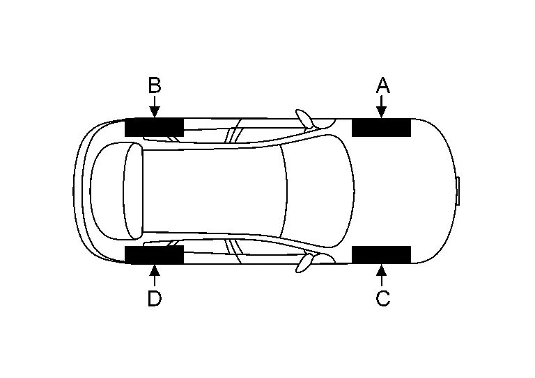
Mark points ãAã, ãBã, ãCã and ãDã at the center position of each wheels.
-
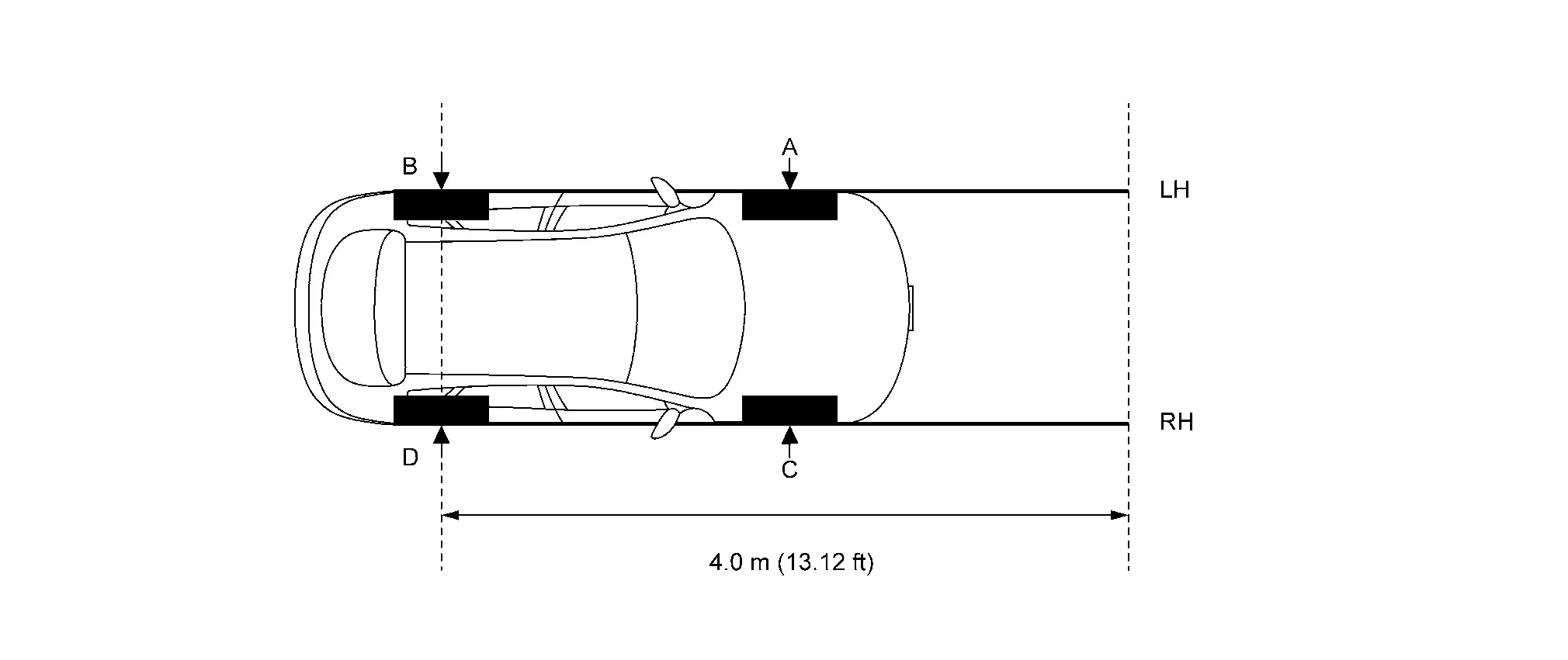
Draw line "LH (RH)" passing through points "A (C)" and "B (D)" on the left (right) side of Nissan Ariya vehicle.
 NOTE:
NOTE:
Approximately 4.0 m (13.12 ft) or more from the point "B (D)".
-
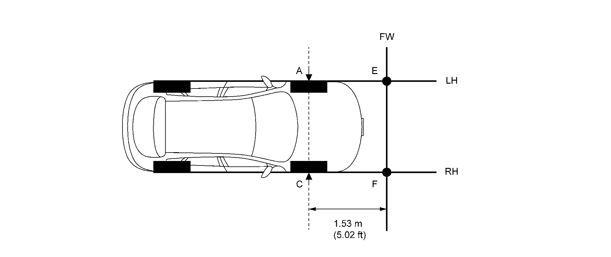
Mark point "E (F)" on the line "LH (RH)" at the positions 1.53 m (5.02 in) from point "A (C)". And then draw line "FW" passing through the points "E" and "F".
-
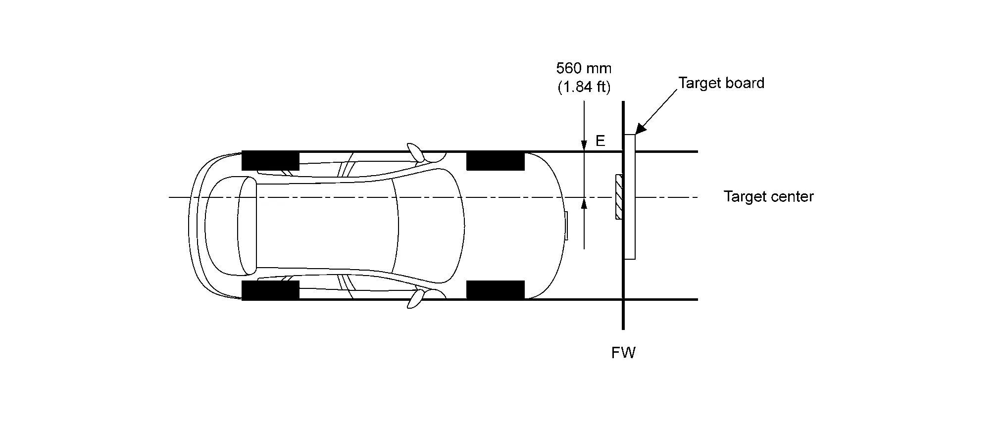
Place the target board on the line "FW" so that the center of the target comes to 560 mm (1.84 ft) from mark point "E".
>>
GO TO 3.
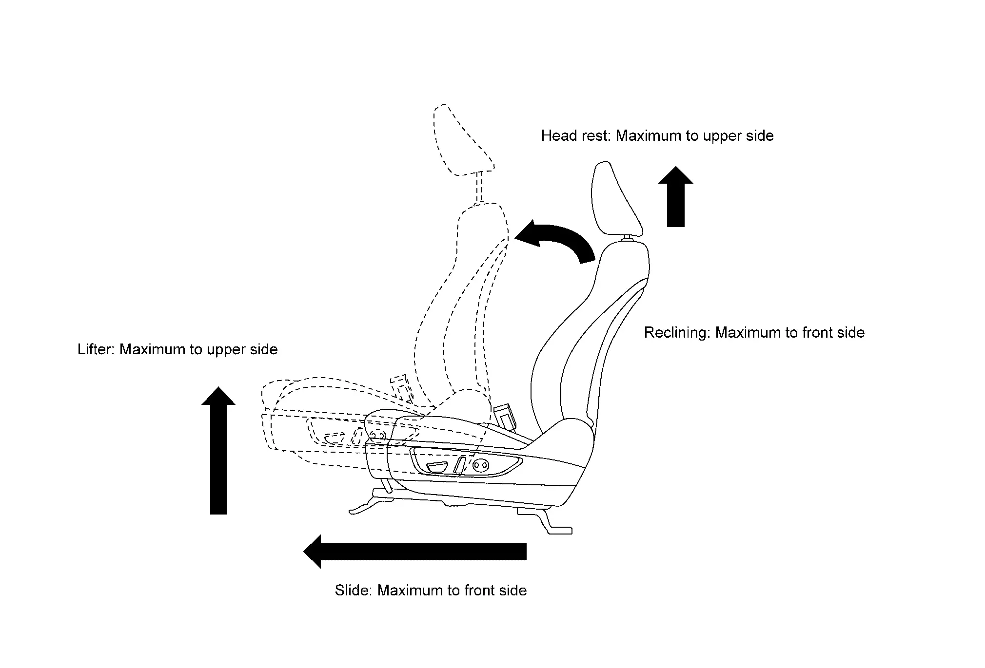
DRIVER'S SEAT POSITION ADJUSTMENT
Adjust the driver's seat to the position shown in the figure.
>>
GO TO 4.
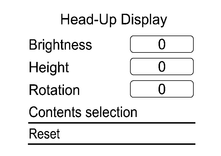
RESET OPERATION
-
Ignition switch ON.
-
Select "Reset" on the Head Up Display setting screen of the combination meter and reset the setting. Refer to Switch Name and Function.
>>
GO TO 5.
TARGET CENTER POSITION ADJUSTMENT
CONSULT
-
Select "Distortion calibration" of "Work Support" on "HEAD UP DISPLAY".
-
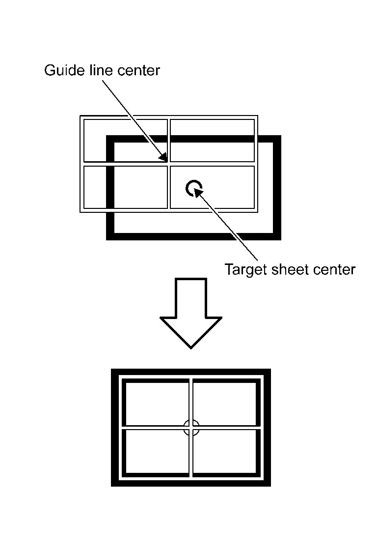
Confirm from the between seatback and headrest whether the center position of the displayed guideline is coincident with the center position of the target sheet.
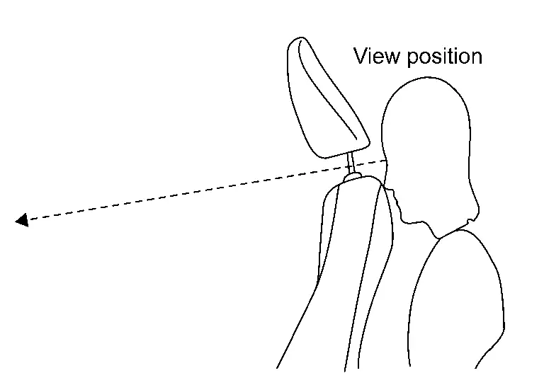
NOTE:
If there is a gap between the target sheet and the guideline, move the target board so that the center of the target seat coincides with the center of the guideline.
>>
GO TO 6.
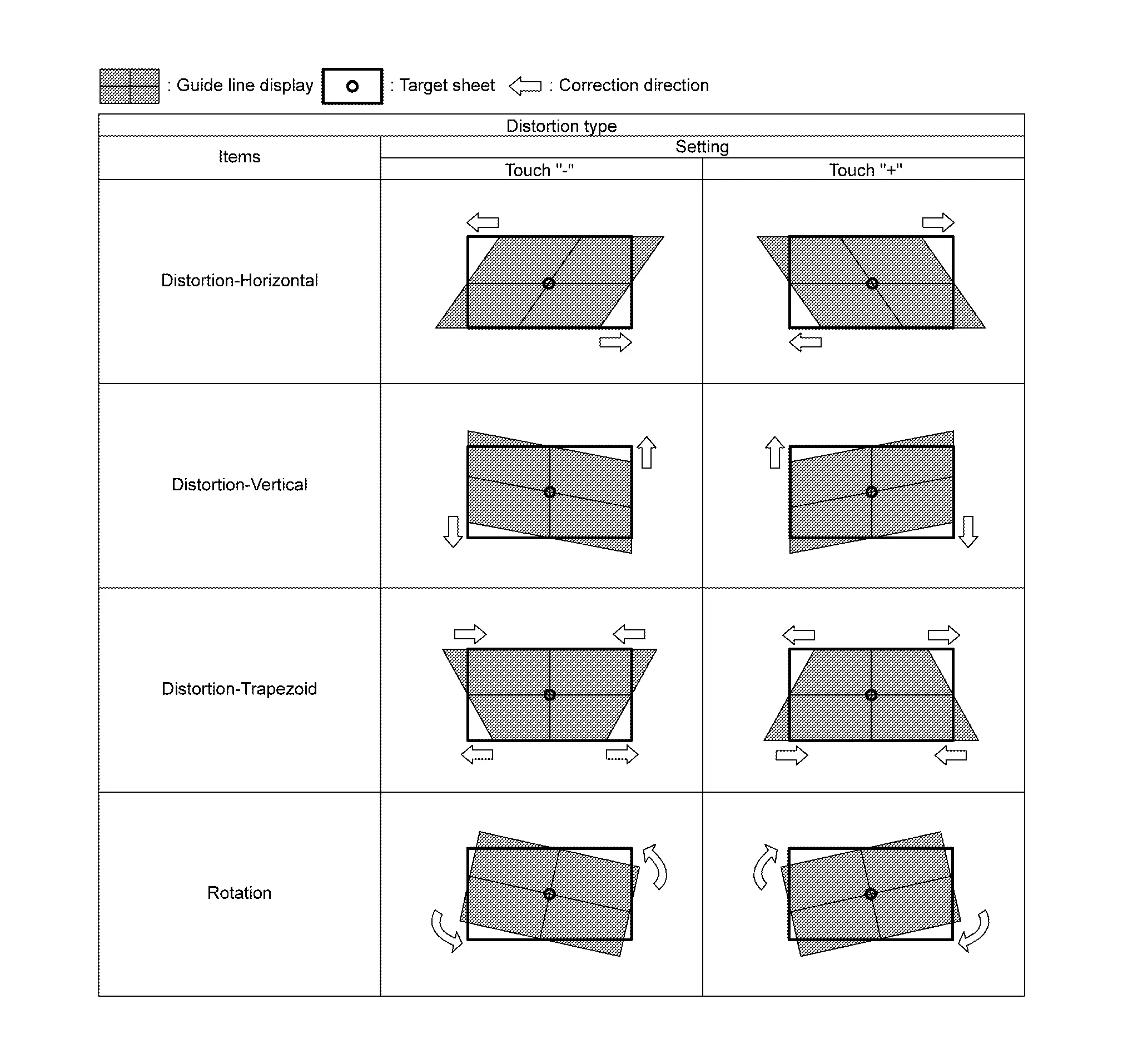
PERFORM DISTORTION CALIBRATION
CONSULT
-
Check the distortion of the guideline from the between seatback and headrest.

-
If the guideline display is distorted, touch "+" or "-" of the item corresponding to the distortion type to be corrected according to following table, and calibrate to match the target sheet.
-
Select "Save" and save the setting when calibration is completed.
NOTE:
Select "Reset" to cancel the change.
>>
Work End.
Other materials:
System Description. System (back Door Opener System)
System Description
SYSTEM DIAGRAM Component Function
Back door opener switch
Refer to Back Door Opener Switch.
Back door opener actuator
Refer to Back Door Lock Assembly.
ABS actuator and electric unit (control unit)
Transmit Nissan Ariya vehicle speed signal to BCM via CAN c ...
Symptom Diagnosis. Ignition Position Warning Function Does Not Operate
Diagnosis Procedure
CHECK POWER DOOR LOCK OPERATION
Check door lock/unlock using door lock/unlock switch.
Does door lock/unlock with door lock/unlock switch?
YES>>
GO TO 2.
NO>>
Refer to Diagnosis Procedure.
CHECK DOOR SWITCH
Check front door switch (front LH).
Refer to Compo ...
Systû´me d'essuie-glace automatique avec dûˋtecteur de pluie du Nissan Rogue
Le Nissan Rogue est dotûˋ d'une technologie de dûˋtection de prûˋcipitations intelligente. Ce systû´me d'essuie-glace automatique, assistûˋ par un capteur de pluie optique situûˋ sur la partie supûˋrieure du pare-brise (derriû´re le rûˋtroviseur intûˋrieur), est capable d'activer les balais sa ...