Nissan Rogue (T33) 2021-Present Service Manual: Transmission (tcm)
P0604-00 Control Module Ram
DTC Description
DTC DETECTION LOGIC
| DTC |
CONSULT screen terms (Trouble diagnosis content) |
DTC detection condition | ||
| P0604 | 00 |
Control module RAM [Internal Control Module Read Access Memory (RAM) Error] |
Diagnosis condition | When the ignition switch is ON |
| Signal | ŌĆö | |||
| Threshold | TCM RAM area sum parity check detects malfunction in RAM. | |||
| Diagnosis delay time | ŌĆö | |||
POSSIBLE CAUSE
TCM (RAM)
FAIL-SAFE
-
Selector shock is large
-
Start is slow
-
Acceleration is slow
-
Lock-up is not performed
-
Stop/start system prohibited*
*: With stop/start system
DTC CONFIRMATION PROCEDURE
PREPARATION BEFORE WORK
If another "DTC CONFIRMATION PROCEDURE" occurs just before, ignition switch OFF and wait for at least 10 seconds, then perform the next test.
TESTING CONDITION:
Before performing the following procedure, confirm that battery voltage is more than 10 V.
>>
GO TO 2.
PERFORM DTC CONFIRMATION PROCEDURE
-
Ignition switch ON.
-
Check the DTC.
Is DTC detected?
YES>>Proceed to Diagnosis Procedure.
NO-1>>To check malfunction symptom before repair: Refer to Intermittent Incident.
NO-2>>Confirmation after repair: INSPECTION END
DTC Diagnosis Procedure
REPLACE TCM
Replace TCM. Refer to Removal and Installation.
>>
WORK END
P0605-00 Control Module Rom
DTC Description
DTC DETECTION LOGIC
| DTC |
CONSULT screen terms (Trouble diagnosis content) |
DTC detection condition | ||
| P0605 | 00 |
Control module ROM [Internal Control Module Read Access Memory (ROM) Error] |
Diagnosis condition | When the ignition switch is ON |
| Signal | ŌĆö | |||
| Threshold | TCM ROM area sum parity check detects malfunction in ROM. | |||
| Diagnosis delay time | ŌĆö | |||
POSSIBLE CAUSE
TCM (ROM)
FAIL-SAFE
-
Selector shock is large
-
Start is slow
-
Acceleration is slow
-
Lock-up is not performed
-
Stop/start system prohibited*
*: With stop/start system
DTC CONFIRMATION PROCEDURE
PREPARATION BEFORE WORK
If another "DTC CONFIRMATION PROCEDURE" occurs just before, ignition switch OFF and wait for at least 10 seconds, then perform the next test.
TESTING CONDITION:
Before performing the following procedure, confirm that battery voltage is more than 10 V.
>>
GO TO 2.
PERFORM DTC CONFIRMATION PROCEDURE
-
Ignition switch ON.
-
Check the DTC.
Is DTC detected?
YES>>Proceed to Diagnosis Procedure.
NO-1>>To check malfunction symptom before repair: Refer to Intermittent Incident.
NO-2>>Confirmation after repair: INSPECTION END
DTC Diagnosis Procedure
REPLACE TCM
Replace TCM. Refer to Removal and Installation.
>>
WORK END
P0606-00 Control Module
DTC Description
DTC DETECTION LOGIC
| DTC |
CONSULT screen terms (Trouble diagnosis content) |
DTC detection condition | ||
| P0606 | 00 |
Control module processor (Control Module Processor) |
Diagnosis condition | When the ignition switch is ON |
| Signal | ŌĆö | |||
| Threshold |
One of the following error information in micro-controller is satisfied. a) CPU diagnosis error. b) Memory access diagnosis error. c) Clock diagnosis error. d) Program flow diagnosis error |
|||
| Diagnosis delay time | ŌĆö | |||
POSSIBLE CAUSE
TCM
FAIL-SAFE
-
Selector shock is large
-
Start is slow
-
Acceleration is slow
-
Lock-up is not performed
-
Stop/start system prohibited*
*: With stop/start system
DTC CONFIRMATION PROCEDURE
PREPARATION BEFORE WORK
If another "DTC CONFIRMATION PROCEDURE" occurs just before, ignition switch OFF and wait for at least 10 seconds, then perform the next test.
TESTING CONDITION:
Before performing the following procedure, confirm that battery voltage is more than 10 V.
>>
GO TO 2.
PERFORM DTC CONFIRMATION PROCEDURE
-
Ignition switch ON.
-
Check the DTC.
Is DTC detected?
YES>>Proceed to Diagnosis Procedure.
NO-1>>To check malfunction symptom before repair: Refer to Intermittent Incident.
NO-2>>Confirmation after repair: INSPECTION END
DTC Diagnosis Procedure
REPLACE TCM
Replace TCM. Refer to Removal and Installation.
>>
WORK END
P060a-00 Control Module
DTC Description
DTC DETECTION LOGIC
| DTC |
CONSULT screen terms (Trouble diagnosis content) |
DTC detection condition | ||
| P060A | 00 |
Internal control module monitoring processor (Internal Control Module Monitoring Processor Performance) |
Diagnosis condition | When the ignition switch is ON |
| Signal | ŌĆö | |||
| Threshold |
One of the following error information in micro-controller is satisfied. a) CPU diagnosis error. b) Analog-to-digital converter functional diagnosis error. c) Watchdog timar diagnosis error. d) Sub micro-controller diagnosis error. e) Communication diagnosis error between micro-controller and sub micro-controller. f) Blocking diagnosis error of power supply for solenoid. g) Blocking diagnosis error of CAN communication. |
|||
| Diagnosis delay time | ŌĆö | |||
POSSIBLE CAUSE
TCM
FAIL-SAFE
-
Selector shock is large
-
Start is slow
-
Acceleration is slow
-
Lock-up is not performed
DTC CONFIRMATION PROCEDURE
PREPARATION BEFORE WORK
If another "DTC CONFIRMATION PROCEDURE" occurs just before, ignition switch OFF and wait for at least 10 seconds, then perform the next test.
TESTING CONDITION:
Before performing the following procedure, confirm that battery voltage is more than 10 V.
>>
GO TO 2.
PERFORM DTC CONFIRMATION PROCEDURE
-
Ignition switch ON.
-
Check the DTC.
Is DTC detected?
YES>>Proceed to Diagnosis Procedure.
NO-1>>To check malfunction symptom before repair: Refer to Intermittent Incident.
NO-2>>Confirmation after repair: INSPECTION END
Diagnosis Procedure
REPLACE TCM
Replace TCM. Refer to Removal and Installation.
>>
WORK END
P062f-00 Eeprom
DTC Description
DTC DETECTION LOGIC
| DTC |
CONSULT screen terms (Trouble diagnosis content) |
DTC detection condition | ||
| P062F | 00 |
Control module EEPROM (Internal Control Module EEPROM Error) |
Diagnosis condition | When turning ON the ignition switch. |
| Signal | ŌĆö | |||
| Threshold | Flash ROM error is detected | |||
| Diagnosis delay time | Immediately | |||
POSSIBLE CAUSE
TCM (Flash ROM)
FAIL-SAFE
Stop/start system prohibited*
*: With stop/start system
DTC CONFIRMATION PROCEDURE
PREPARATION BEFORE WORK
If another "DTC CONFIRMATION PROCEDURE" occurs just before, ignition switch OFF and wait for at least 10 seconds, then perform the next test.
TESTING CONDITION:
Before performing the following procedure, confirm that battery voltage is more than 10 V.
>>
GO TO 2.
PERFORM DTC CONFIRMATION PROCEDURE
-
Start the engine.
-
Check the DTC.
Is DTC detected?
YES>>Proceed to Diagnosis Procedure.
NO-1>>To check malfunction symptom before repair: Refer to Intermittent Incident.
NO-2>>Confirmation after repair: INSPECTION END
Diagnosis Procedure
REPLACE TCM
Replace TCM. Refer to Removal and Installation.
YES>>
WORK END
P06b1-00 Sensor Power Supply a
DTC Description
DTC DETECTION LOGIC
| DTC | CONSULT screen terms (Trouble diagnosis content) | DTC detection condition | ||
|---|---|---|---|---|
| P06B1 | 00 |
Sensor power supply A (Sensor Power Supply "A" Circuit Low) |
Diagnosis condition | When the ignition switch is ON |
| Signal (terminal) | ŌĆö | |||
| Threshold (Assessment criteria) |
When a detection signal of DTC P06B1-00 is transmitted from the electric shift system.
For the detection condition of DTC P06B1-00, refer to DTC Description. |
|||
| Diagnosis delay time | ŌĆö | |||
POSSIBLE CAUSE
-
Harness or connectors (Electric shift sensor circuits are open or shorted.)
-
Electric shift sensor
-
Electric shift control module
FAIL-SAFE
Determination time of the shift selector position becomes long (1 second or more)
DTC CONFIRMATION PROCEDURE
Refer to DTC P06B1-00 description of electric shift system. Refer to DTC Description.
Diagnosis Procedure
Refer to DTC P06B1-00 diagnosis procedure of electric shift system. Refer to DTC Diagnosis Procedure.
P0705-00 Transmission Range Sensor a
DTC Description
DTC DETECTION LOGIC
| DTC |
CONSULT screen terms (Trouble diagnosis content) |
DTC detection condition | ||
| P0705 | 00 |
Transmission range sensor A [Transmission Range Sensor "A" Circuit (PRNDL Input)] |
Diagnosis condition | Power supply voltage Ōēź 10 V |
| Signal | Transmission range switch signal | |||
| Threshold | When there is undefined range pattern input | |||
| Diagnosis delay time | 2 seconds | |||
POSSIBLE CAUSE
-
Harness or connector
-
Transmission range switch
-
TCM
FAIL-SAFE
-
Shift position indicator on combination meter is not displayed
-
Powertrain becomes neutral
-
Stop/start system prohibited*
*: With stop/start system
DTC CONFIRMATION PROCEDURE
PREPARATION BEFORE WORK
If another "DTC CONFIRMATION PROCEDURE" occurs just before, ignition switch OFF and wait for at least 10 seconds, then perform the next test.
TESTING CONDITION:
Before performing the following procedure, confirm that battery voltage is more than 10 V.
>>
GO TO 2.
PERFORM DTC CONFIRMATION PROCEDURE
-
Start the engine.
-
Depress the brake pedal.
-
Shift the selector lever to "R" position and wait for 5 seconds or more.
-
Shift the selector lever to "N" position and wait for 5 seconds or more.
-
Shift the selector lever to "D/M" position and wait for 5 seconds or more.
-
Press P position switch and wait for 5 seconds or more.
-
Check the DTC.
Is DTC detected?
YES>>Proceed to Diagnosis Procedure.
NO-1>>To check malfunction symptom before repair: Refer to Intermittent Incident.
NO-2>>Confirmation after repair: INSPECTION END
Diagnosis Procedure
CHECK TRANSMISSION RANGE SWITCH CIRCUIT
Check transmission range switch circuit. Refer to Diagnosis Procedure.
>>
INSPECTION END
P0706-00 Transmission Range Sensor a
DTC Description
DTC DETECTION LOGIC
| DTC |
CONSULT screen terms (Trouble diagnosis content) |
DTC detection condition | ||
| P0706 | 00 |
Transmission range sensor A (Transmission Range Sensor "A" Circuit Range/Performance) |
Diagnosis condition | Power supply voltage Ōēź 10 V |
| Signal | Transmission range switch signal | |||
| Threshold | When there is range pattern input of intermediate range | |||
| Diagnosis delay time | 2 seconds | |||
POSSIBLE CAUSE
-
Harness or connector
-
Transmission range switch
-
TCM
FAIL-SAFE
-
Shift position indicator on combination meter is not displayed
-
Powertrain becomes neutral
-
Stop/start system prohibited*
*: With stop/start system
DTC CONFIRMATION PROCEDURE
PREPARATION BEFORE WORK
If another "DTC CONFIRMATION PROCEDURE" occurs just before, ignition switch OFF and wait for at least 10 seconds, then perform the next test.
TESTING CONDITION:
Before performing the following procedure, confirm that battery voltage is more than 10 V.
>>
GO TO 2.
PERFORM DTC CONFIRMATION PROCEDURE
-
Start the engine.
-
Depress the brake pedal.
-
Shift the selector lever to "R" position and wait for 5 seconds or more.
-
Shift the selector lever to "N" position and wait for 5 seconds or more.
-
Shift the selector lever to "D/M" position and wait for 5 seconds or more.
-
Press P position switch and wait for 5 seconds or more.
-
Check the DTC.
Is DTC detected?
YES>>Proceed to Diagnosis Procedure.
NO-1>>To check malfunction symptom before repair: Refer to Intermittent Incident.
NO-2>>Confirmation after repair: INSPECTION END
Diagnosis Procedure
CHECK TRANSMISSION RANGE SWITCH CIRCUIT
Check transmission range switch circuit. Refer to Diagnosis Procedure.
>>
INSPECTION END
P0711-00 Transmission Fluid Temperature Sensor a
DTC Description
DTC DETECTION LOGIC
| DTC |
CONSULT screen terms (Trouble diagnosis content) |
DTC detection condition | |||
| P0711 | 00 |
Transmission fluid temperature sensor A (Transmission Fluid Temperature Sensor A Circuit Range/Performance) |
1 | Diagnosis condition |
Diagnosis is permitted when all of the following conditions are satisfied: a) Power supply voltage: More than 11 V b) CAN communication is normal d) Accelerator pedal position: 3 deg or more e) Nissan Ariya Vehicle speed: 10 km/h (7 MPH) or more f) Shift position: D position |
| Signal | CVT fluid temperature sensor signal | ||||
| Threshold | CVT fluid temperature does not rise to 10┬░C (50┬░F) after driving for a certain period of time with the TCM-received fluid temperature sensor value between ŌłÆ 40┬░C (ŌłÆ40┬░F) and 9┬░C (48.2┬░F). | ||||
| Diagnosis delay time | ŌĆö | ||||
| 2 | Diagnosis condition |
Diagnosis is permitted when all of the following conditions satisfied: a) Power supply voltage: 11 V or more b) The difference between CVT fluid temperature and engine coolant temperature is 44┬░C (111┬░F) or more, or ŌłÆ27┬░C (ŌłÆ16┬░F) or less. c) Engine speed: 305 rpm or more |
|||
| Signal | CVT fluid temperature sensor signal | ||||
| Threshold |
DTC is detected when all of the following conditions are satisfied: a) ECM is normal. b) Diagnosis condition is satisfied. |
||||
| Diagnosis delay time | 300 seconds | ||||
POSSIBLE CAUSE
-
Harness or connector
-
CVT fluid temperature sensor
-
TCM
FAIL-SAFE
-
Engine coolant temperature when engine start: Temp. Ōēź 10┬░C (50┬░F)
-
Start is slow
-
Acceleration is slow
-
-
Engine coolant temperature when engine start: ŌłÆ35┬░C (ŌłÆ31┬░F) Ōēż Temp. < 10┬░C (50┬░F)
-
Selector shock is large
-
Start is slow
-
Acceleration is slow
-
-
Engine coolant temperature when engine start: Temp. <ŌłÆ35┬░C (ŌłÆ31┬░F)
-
Selector shock is large
-
Start is slow
-
Acceleration is slow
-
-
Stop/start system prohibited*
*: With stop/start system
DTC CONFIRMATION PROCEDURE
CAUTION:
Always drive vehicle at a safe speed.
PREPARATION BEFORE WORK
If another "DTC CONFIRMATION PROCEDURE" occurs just before, ignition switch is OFF and wait for at least 10 seconds, then perform the next test.
>>
GO TO 2.
INSPECTION START
Is it necessary to erase permanent DTC?
YES>>GO TO 3.
NO>>GO TO 7.
CHECK DTC (ECM AND TCM)
Check the DTC.
Is any DTC other than ŌĆ£P0711ŌĆō00ŌĆØ detected?
YES>>Check DTC detected item. Refer to DTC Index (ECM), DTC Index (TCM).
NO>>GO TO 4.
PERFORM DTC CONFIRMATION PROCEDURE (PART 1)
TESTING CONDITION:
-
While performing the following procedure, never add fuel.
-
Before performing the following procedure, check that fuel level is between 1/4 and 4/4.
-
Before performing the following procedure, confirm that battery voltage is 11 V or more at idle.
 With CONSULT
-
Move the Nissan Ariya vehicle to a cool place.
 NOTE:
NOTE:
Cool the vehicle in an environment of ambient air temperature between ŌłÆ10┬░C (14┬░F) and 35┬░C (95┬░F).
-
Ignition switch OFF and leave the Nissan Ariya vehicle for 12 hours.
CAUTION:
Never the ignition switch is ON during this procedure.
NOTE:
The Nissan Ariya vehicle must be cooled with the food open.
-
Ignition switch ON.
CAUTION:
Never start the engine.
-
Select ŌĆ£Data MonitorŌĆØ in ŌĆ£TRANSMISSIONŌĆØ.
-
Select ŌĆ£Transmission fluid temperatureŌĆØ.
-
Record CVT fluid temperature.
-
Start engine and let it idle for 5 minutes or more.
CAUTION:
Never the ignition switch is OFF during idling.
-
Check 1st trip DTC.
 With GST
-
Move the Nissan Ariya vehicle to a cool place.
NOTE:
Cool the vehicle in an environment of ambient air temperature between ŌłÆ10┬░C (14┬░F) and 35┬░C (95┬░F).
-
Ignition switch OFF and leave the Nissan Ariya vehicle for 12 hours.
CAUTION:
Never the ignition switch is ON during this procedure.
NOTE:
The Nissan Ariya vehicle must be cooled with the food open.
-
Start engine and let it idle for 5 minutes or more.
CAUTION:
Never the ignition switch is OFF during idling.
-
Check 1st trip DTC.
Is ŌĆ£P0711ŌĆō00ŌĆØ detected?
YES>>Go to Diagnosis Procedure.
NO-1>>With CONSULT: GO TO 5.
NO-2>>With GST: GO TO 6.
CHECK CVT FLUID TEMPERATURE
With CONSULT
-
Select ŌĆ£Data MonitorŌĆØ in ŌĆ£TRANSMISSIONŌĆØ.
-
Select ŌĆ£Transmission fluid temperatureŌĆØ.
Is the value of ŌĆ£Transmission fluid temperatureŌĆØ 10┬░C (50┬░F) or more?
YES>>INSPECTION END
NO>>GO TO 6.
PERFORM DTC CONFIRMATION PROCEDURE (PART 2)
With CONSULT
-
Drive the Nissan Ariya vehicle for the total minutes specified in the Driving time column below with the following conditions satisfied.
Shift position : ŌĆ£DŌĆØ position Accelerator pedal position : 1.0/8 or more Nissan Ariya Vehicle speed : 10 km/h (7 MPH) or more CVT fluid temperature before engine start Driving time ŌłÆ40┬░C (ŌłÆ40┬░F) ŌĆōŌłÆ31┬░C (ŌłÆ23.8┬░F) 20 minutes or more ŌłÆ30┬░C (ŌłÆ22┬░F) ŌĆōŌłÆ21┬░C (ŌłÆ5.8┬░F) 18 minutes or more ŌłÆ20┬░C (ŌłÆ4┬░F) ŌĆōŌłÆ11┬░C (ŌłÆ12.2┬░F) 14 minutes or more ŌłÆ10┬░C (14┬░F) ŌĆōŌłÆ1┬░C (30.2┬░F) 10 minutes or more 0┬░C (32┬░F) ŌĆō 9┬░C (48.2┬░F) 7 minutes or more -
Stop the Nissan Ariya vehicle.
-
Check the first trip DTC.
With GST
-
Drive the Nissan Ariya vehicle and maintain the following conditions for 20 minutes or more.
Shift position : ŌĆ£DŌĆØ position Accelerator pedal position : 1.0/8 or more Nissan Ariya Vehicle speed : 10 km/h (7 MPH) or more -
Stop the vehicle.
-
Check the first trip DTC.
Is ŌĆ£P0711ŌĆō00ŌĆØ detected?
YES>>Go to Diagnosis Procedure.
NO-1>>To check malfunction symptom before repair: Refer to Intermittent Incident.
NO-2>>Confirmation after repair: INSPECTION END
PERFORM DTC CONFIRMATION PROCEDURE
With CONSULT
-
Ignition switch OFF and cool the engine.
-
Ignition switch ON.
CAUTION:
Never start the engine.
-
Select ŌĆ£Data MonitorŌĆØ in ŌĆ£TRANSMISSIONŌĆØ.
-
Select ŌĆ£Transmission fluid temperatureŌĆØ.
-
Record CVT fluid temperature.
-
Start the engine and wait for at least 2 minutes.
-
Drive the Nissan Ariya vehicle for the total minutes specified in the Driving time column below with the following conditions satisfied.
Shift position : ŌĆ£DŌĆØ position Accelerator pedal position : 1.0/8 or more Nissan Ariya Vehicle speed : 10 km/h (7 MPH) or more CVT fluid temperature before engine start Driving time ŌłÆ40┬░C (ŌłÆ40┬░F) ŌĆōŌłÆ31┬░C (ŌłÆ23.8┬░F) 20 minutes or more ŌłÆ30┬░C (ŌłÆ22┬░F) ŌĆōŌłÆ21┬░C (ŌłÆ5.8┬░F) 18 minutes or more ŌłÆ20┬░C (ŌłÆ4┬░F) ŌĆōŌłÆ11┬░C (ŌłÆ12.2┬░F) 14 minutes or more ŌłÆ10┬░C (14┬░F) ŌĆōŌłÆ1┬░C (30.2┬░F) 10 minutes or more 0┬░C (32┬░F) ŌĆō 9┬░C (48.2┬░F) 7 minutes or more Other than the above ŌĆö (Go to ŌĆ£8.CHECK CVT FLUID TEMPERATURE SENSORŌĆØ) -
Stop the Nissan Ariya vehicle.
-
Check the first trip DTC.
With GST
-
Ignition switch OFF and cool the engine.
-
Start the engine and wait for at least 2 minutes.
-
Drive the Nissan Ariya vehicle and maintain the following conditions for 20 minutes or more.
Shift position : ŌĆ£DŌĆØ position Accelerator pedal position : 1.0/8 or more Nissan Ariya Vehicle speed : 10 km/h (7 MPH) or more -
Stop the vehicle.
CAUTION:
Never the ignition switch is OFF
-
Check the first trip DTC.
Is ŌĆ£P0711ŌĆō00ŌĆØ detected?
YES>>Go to Diagnosis Procedure.
NO>>GO TO 8.
CHECK CVT FLUID TEMPERATURE SENSOR
-
Ignition switch is OFF.
-
Remove TCM. Refer to Removal and Installation
-
Check resistance between TCM harness connector terminals.
TCM Condition Resistance
(Approx.)Connector Terminal F115 5 ŌĆō 12 CVT fluid temperature: 20┬░C (68┬░F) 6.5 kŌä” CVT fluid temperature: 50┬░C (122┬░F) 2.2 kŌä”
Is the inspection result normal?
YES-1>>To check malfunction symptom before repair: Refer to Intermittent Incident.
YES-2>>Confirmation after repair: INSPECTION END
NO>>There is a malfunction of CVT fluid temperature sensor. Replace terminal cord assembly. Refer to Removal and Installation.
Diagnosis Procedure
CHECK CVT FLUID TEMPERATURE SENSOR CIRCUIT
Check CVT fluid temperature sensor circuit. Refer to Diagnosis Procedure.
>>
INSPECTION END
P0712-00 Transmission Fluid Temperature Sensor a
DTC Description
DTC DETECTION LOGIC
| DTC |
CONSULT screen terms (Trouble diagnosis content) |
DTC detection condition | ||
| P0712 | 00 |
Transmission fluid temperature sensor A (Transmission Fluid Temperature Sensor "A" Circuit Low) |
Diagnosis condition |
Diagnosis is permitted when all of the following conditions are satisfied: a) Power supply voltage Ōēź 10 V b) Nissan Ariya Vehicle speed Ōēź 0 km/h (0 MPH) |
| Signal | CVT fluid temperature signal | |||
| Threshold | CVT fluid temperature sensor detecting voltage Ōēż 0.15 V [CVT fluid temperature Ōēź 180 ┬░C (356 ┬░F)] | |||
| Diagnosis delay time | 5 seconds | |||
POSSIBLE CAUSE
-
Harness or connector
-
CVT fluid temperature sensor
-
TCM
FAIL-SAFE
-
Engine coolant temperature when engine start: Temp. Ōēź 10┬░C (50┬░F)
-
Start is slow
-
Acceleration is slow
-
-
Engine coolant temperature when engine start: ŌłÆ35┬░C (ŌłÆ31┬░F) Ōēż Temp. < 10┬░C (50┬░F)
-
Selector shock is large
-
Start is slow
-
Acceleration is slow
-
-
Engine coolant temperature when engine start: Temp. <ŌłÆ35┬░C (ŌłÆ31┬░F)
-
Selector shock is large
-
Start is slow
-
Acceleration is slow
-
-
Stop/start system prohibited*
*: With stop/start system
DTC CONFIRMATION PROCEDURE
PREPARATION BEFORE WORK
If another "DTC CONFIRMATION PROCEDURE" occurs just before, ignition switch OFF and wait for at least 10 seconds, then perform the next test.
TESTING CONDITION:
Before performing the following procedure, confirm that battery voltage is more than 10 V.
>>
GO TO 2.
PERFORM DTC DETECTION
-
Start the engine.
-
Drive the Nissan Ariya vehicle and maintain the following condition for 10 seconds or more.
Nissan Ariya Vehicle speed : 10 km/h (6 MPH) or more CAUTION:
Be careful of the driving speed.
-
Stop the Nissan Ariya vehicle.
-
Check the DTC.
Is DTC detected?
YES>>Proceed to Diagnosis Procedure.
NO-1>>To check malfunction symptom before repair: Refer to Intermittent Incident.
NO-2>>Confirmation after repair: INSPECTION END
Diagnosis Procedure
CHECK CVT FLUID TEMPERATURE SENSOR CIRCUIT
Check CVT fluid temperature sensor circuit. Refer to Diagnosis Procedure.
>>
INSPECTION END
P0713-00 Transmission Fluid Temperature Sensor a
DTC Description
DTC DETECTION LOGIC
| DTC |
CONSULT screen terms (Trouble diagnosis content) |
DTC detection condition | ||
| P0713 | 00 |
Transmission fluid temperature sensor A (Transmission Fluid Temperature Sensor "A" Circuit High) |
Diagnosis condition |
Diagnosis is permitted when all of the following conditions are satisfied: a) Power supply voltage Ōēź 10 V b) Nissan Ariya Vehicle speed Ōēź 10 km/h (6 MPH) |
| Signal | CVT fluid temperature signal | |||
| Threshold | CVT fluid temperature sensor detecting voltage Ōēź 2.48 V [CVT fluid temperature Ōēż -40 ┬░C (-40 ┬░F)] | |||
| Diagnosis delay time | 5 seconds | |||
POSSIBLE CAUSE
-
Harness or connector
-
CVT fluid temperature sensor
-
TCM
FAIL-SAFE
-
Engine coolant temperature when engine start: Temp. Ōēź 10┬░C (50┬░F)
-
Start is slow
-
Acceleration is slow
-
-
Engine coolant temperature when engine start: ŌłÆ35┬░C (ŌłÆ31┬░F) Ōēż Temp. < 10┬░C (50┬░F)
-
Selector shock is large
-
Start is slow
-
Acceleration is slow
-
-
Engine coolant temperature when engine start: Temp. <ŌłÆ35┬░C (ŌłÆ31┬░F)
-
Selector shock is large
-
Start is slow
-
Acceleration is slow
-
-
Stop/start system prohibited*
*: With stop/start system
DTC CONFIRMATION PROCEDURE
PREPARATION BEFORE WORK
If another "DTC CONFIRMATION PROCEDURE" occurs just before, ignition switch OFF and wait for at least 10 seconds, then perform the next test.
TESTING CONDITION:
Before performing the following procedure, confirm that battery voltage is more than 10 V.
>>
GO TO 2.
PERFORM DTC DETECTION
-
Start the engine.
-
Drive the Nissan Ariya vehicle and maintain the following condition for 10 seconds or more.
Nissan Ariya Vehicle speed : 10 km/h (6 MPH) or more CAUTION:
Be careful of the driving speed.
-
Stop the Nissan Ariya vehicle.
-
Check the DTC.
Is DTC detected?
YES>>Proceed to Diagnosis Procedure.
NO-1>>To check malfunction symptom before repair: Refer to Intermittent Incident.
NO-2>>Confirmation after repair: INSPECTION END
Diagnosis Procedure
CHECK CVT FLUID TEMPERATURE SENSOR CIRCUIT
Check CVT fluid temperature sensor circuit. Refer to Diagnosis Procedure.
>>
INSPECTION END
P0715-00 Input Speed Sensor a
DTC Description
DTC DETECTION LOGIC
| DTC |
CONSULT screen terms (Trouble diagnosis content) |
DTC detection condition | ||
| P0715 | 00 |
Input/Turbine shaft speed sensor A (Input/Turbine Shaft Speed Sensor "A" Circuit) |
Diagnosis condition |
Diagnosis is permitted when all of the following conditions are satisfied: a) Ignition voltage Ōēź 9.01 V b) Battery voltage Ōēź 9.01 V |
| Signal | Input speed sensor signal | |||
| Threshold |
DTC is detected when one of the following conditions a) to b) are satisfied: Input speed sensor signal voltage: a) 4.311 V Ōēż sensor signal < 4.6 V b) 0.108 V Ōēż sensor signal < 0.719 V |
|||
| Diagnosis delay time | 0.2 seconds | |||
POSSIBLE CAUSE
-
Harness or connector
-
Input speed sensor
-
TCM
FAIL-SAFE
-
Lock-up is not performed
-
Stop/start system prohibited*
*: With stop/start system
DTC CONFIRMATION PROCEDURE
PREPARATION BEFORE WORK
If another "DTC CONFIRMATION PROCEDURE" occurs just before, ignition switch OFF and wait for at least 10 seconds, then perform the next test.
TESTING CONDITION:
Before performing the following procedure, confirm that battery voltage is more than 10 V.
>>
GO TO 2.
PERFORM DTC DETECTION
-
Start the engine.
-
Drive the Nissan Ariya vehicle and maintain the following conditions for 10 seconds or more.
Shift position : "D" position Nissan Ariya Vehicle speed : 40 km/h (25 MPH) or more CAUTION:
Be careful of the driving speed.
-
Stop the Nissan Ariya vehicle.
-
Check the DTC.
Is DTC detected?
YES>>Proceed to Diagnosis Procedure.
NO-1>>To check malfunction symptom before repair: Refer to Intermittent Incident.
NO-2>>Confirmation after repair: INSPECTION END
Diagnosis Procedure
CHECK INPUT SPEED SENSOR CIRCUIT
Check input speed sensor circuit. Refer to Diagnosis Procedure.
>>
INSPECTION END
P0716-00 Input Speed Sensor a
DTC Description
DTC DETECTION LOGIC
| DTC |
CONSULT screen terms (Trouble diagnosis content) |
DTC detection condition | ||
| P0716 | 00 |
Input/Turbine shaft speed sensor A (Input/Turbine Shaft Speed Sensor "A" Circuit Range/Performance) |
Diagnosis condition |
Diagnosis is permitted when all of the following conditions are satisfied: a) Ignition voltage Ōēź 9.01 V b) Battery voltage Ōēź 9.01 V c) Range : D d) Primary and secondary pulley speed sensors: Normal e) Primary pulley speed > 300 rpm f) Secondary pulley speed > 860 rpm g) Engine speed Ōē¦ 450 rpm |
| Signal | Input speed sensor signal | |||
| Threshold |
DTC is detected when one of the following conditions a) to b) are satisfied: a) Current pulse frequency / Last pulse frequency Ōēź2 b) Current pulse frequency / Last pulse frequency Ōēż1/2 |
|||
| Diagnosis delay time | ŌĆö | |||
POSSIBLE CAUSE
-
Harness or connector
-
Input speed sensor (source reading input speed sensor value)
-
TCM
FAIL-SAFE
-
Lock-up is not performed
-
Stop/start system prohibited*
*: With stop/start system
DTC CONFIRMATION PROCEDURE
PREPARATION BEFORE WORK
If another "DTC CONFIRMATION PROCEDURE" occurs just before, ignition switch OFF and wait for at least 10 seconds, then perform the next test.
TESTING CONDITION:
Before performing the following procedure, confirm that battery voltage is more than 10 V.
>>
GO TO 2.
PERFORM DTC DETECTION
-
Start the engine.
-
Drive the Nissan Ariya vehicle and maintain the following conditions for 10 seconds or more.
Shift position : "D" position Nissan Ariya Vehicle speed : 40 km/h (25 MPH) or more CAUTION:
Be careful of the driving speed.
-
Stop the Nissan Ariya vehicle.
-
Check the DTC.
Is DTC detected?
YES>>Proceed to Diagnosis Procedure.
NO-1>>To check malfunction symptom before repair: Refer to Intermittent Incident.
NO-2>>Confirmation after repair: INSPECTION END
Diagnosis Procedure
CHECK INPUT SPEED SENSOR CIRCUIT
Check input speed sensor circuit. Refer to Diagnosis Procedure.
>>
INSPECTION END
P0717-00 Input Speed Sensor a
DTC Description
DTC DETECTION LOGIC
| DTC |
CONSULT screen terms (Trouble diagnosis content) |
DTC detection condition | |||
| P0717 | 00 |
Input/Turbine shaft speed sensor A (Input/Turbine Shaft Speed Sensor "A" Circuit No Signal) |
1 | Diagnosis condition |
Diagnosis is permitted when all of the following conditions are satisfied: a) Time passed after changing the range > 2 sec b) Power supply voltage Ōēź 10 V c) Input speed Ōēź 1000 rpm d) Primary pulley speed Ōēź 1000 rpm e) Except N (P) range |
| Signal | Input speed sensor signal | ||||
| Threshold |
DTC is detected when all of the following conditions are satisfied: a) Input speed < 150 rpm b) Primary pulley speed Ōēź 500 rpm |
||||
| Diagnosis delay time | 5 seconds | ||||
| 2 | Diagnosis condition |
Diagnosis is permitted when all of the following conditions are satisfied:
|
|||
| Signal | Input speed sensor signal | ||||
| Threshold |
DTC is detected when all of the following conditions are satisfied: a) Last input speed Ōēź 1000 rpm b) Current input speed Ōēż 240 rpm |
||||
| Diagnosis delay time | 0.5 seconds | ||||
POSSIBLE CAUSE
-
Harness or connector (Input speed sensor circuit is open or shorted)
-
Input speed sensor
-
TCM
-
Control valve
-
Solenoid
FAIL-SAFE
-
Lock-up is not performed
-
Stop/start system prohibited*
*: With stop/start system
DTC CONFIRMATION PROCEDURE
PREPARATION BEFORE WORK
If another "DTC CONFIRMATION PROCEDURE" occurs just before, ignition switch OFF and wait for at least 10 seconds, then perform the next test.
TESTING CONDITION:
Before performing the following procedure, confirm that battery voltage is more than 10 V.
>>
GO TO 2.
PERFORM DTC DETECTION
-
Start the engine.
-
Drive the Nissan Ariya vehicle and maintain the following conditions for 10 seconds or more.
Shift position : "D" position Nissan Ariya Vehicle speed : 40 km/h (25 MPH) or more CAUTION:
Be careful of the driving speed.
-
Stop the Nissan Ariya vehicle.
-
Check the DTC.
Is DTC detected?
YES>>Proceed to Diagnosis Procedure.
NO-1>>To check malfunction symptom before repair: Refer to Intermittent Incident.
NO-2>>Confirmation after repair: INSPECTION END
Diagnosis Procedure
CHECK DTC PRIORITY
When DTC P0717-00 is displayed together with any following DTC, diagnose first the other DTC.
-
P0746-00, P0747-00, P0776-00, P0777-00, P0796-00, P0797-00
Is applicable DTC detected?
YES>>Perform diagnosis of applicable. DTC Index.
NO>>GO TO 2.
CHECK INPUT SPEED SENSOR CIRCUIT
Check input speed sensor circuit. Refer to Diagnosis Procedure.
>>
INSPECTION END
P0718-00 Input Speed Sensor a
DTC Description
DTC DETECTION LOGIC
| DTC |
CONSULT screen terms (Trouble diagnosis content) |
DTC detection condition | ||
| P0718 | 00 |
Input/Turbine shaft speed sensor A (Input/Turbine Shaft Speed Sensor "A" Circuit Intermittent) |
Diagnosis condition |
Diagnosis is permitted when all of the following conditions are satisfied: a) Ignition voltage Ōēź 9.01 V b) Battery voltage Ōēź 9.01 V |
| Signal | Input speed sensor signal | |||
| Threshold | Input speed ’╝× 7300 rpm | |||
| Diagnosis delay time | 2 seconds | |||
POSSIBLE CAUSE
-
Harness or connector
-
Input speed sensor
-
TCM
FAIL-SAFE
Lock-up is not performed
DTC CONFIRMATION PROCEDURE
PREPARATION BEFORE WORK
If another "DTC CONFIRMATION PROCEDURE" occurs just before, ignition switch OFF and wait for at least 10 seconds, then perform the next test.
TESTING CONDITION:
Before performing the following procedure, confirm that battery voltage is more than 10 V.
>>
GO TO 2.
PERFORM DTC DETECTION
-
Start the engine.
-
Drive the Nissan Ariya vehicle and maintain the following conditions for 10 seconds or more.
Shift position : "D" position Nissan Ariya Vehicle speed : 80 km/h (49 MPH) CAUTION:
Be careful of the driving speed.
-
Stop the Nissan Ariya vehicle.
-
Check the DTC.
Is DTC detected?
YES>>Proceed to Diagnosis Procedure.
NO-1>>To check malfunction symptom before repair: Refer to Intermittent Incident.
NO-2>>Confirmation after repair: INSPECTION END
Diagnosis Procedure
CHECK INPUT SPEED SENSOR CIRCUIT
Check input speed sensor circuit. Refer to Diagnosis Procedure.
>>
INSPECTION END
P072a-00 Stuck in Neutral
DTC Description
DTC DETECTION LOGIC
| DTC | CONSULT screen terms (Trouble diagnosis content) | DTC detection condition | ||
|---|---|---|---|---|
| P072A | 00 |
Stuck in neutral (Stuck in Neutral) |
Diagnosis condition | When the ignition switch is ON |
| Signal (terminal) | ŌĆö | |||
| Threshold (Assessment criteria) |
When a detection signal of DTC P072A-00 is transmitted from the electric shift system.
For the detection condition of DTC P072A-00, refer to DTC Description. |
|||
| Diagnosis delay time | ŌĆö | |||
POSSIBLE CAUSE
Transaxle assembly (Sticking of manual shaft)
FAIL-SAFE
Shifting operation is prohibited
DTC CONFIRMATION PROCEDURE
Refer to DTC P072A-00 description of electric shift system. Refer to DTC Description.
Diagnosis Procedure
Refer to DTC P072A-00 diagnosis procedure of electric shift system. Refer to DTC Diagnosis Procedure.
P0740-00 Torque Converter
DTC Description
DTC DETECTION LOGIC
| DTC |
CONSULT screen terms (Trouble diagnosis content) |
DTC detection condition | ||
| P0740 | 00 |
Torque converter clutch (Torque Converter Clutch Circuit/Open) |
Diagnosis condition | Power supply voltage Ōēź 10 V |
| Signal | ŌĆö | |||
| Threshold | Solenoid valve drive circuit is diagnosed as open | |||
| Diagnosis delay time | 0.2 seconds | |||
POSSIBLE CAUSE
-
Harness or connector
-
Torque converter clutch solenoid valve
-
TCM
FAIL-SAFE
-
Start is slow
-
Acceleration is slow
-
Lock-up is not performed
-
Stop/start system prohibited*
*: With stop/start system
DTC CONFIRMATION PROCEDURE
PREPARATION BEFORE WORK
If another "DTC CONFIRMATION PROCEDURE" occurs just before, ignition switch OFF and wait for at least 10 seconds, then perform the next test.
TESTING CONDITION:
Before performing the following procedure, confirm that battery voltage is more than 10 V.
>>
GO TO 2.
PERFORM DTC DETECTION
-
Start the engine.
-
Drive the Nissan Ariya vehicle and maintain the following conditions for 10 seconds or more.
Shift position : "D" position CVT fluid temperature : 20 ┬░C (68 ┬░F) or more Nissan Ariya Vehicle speed : 40 km/h (25 MPH) or more CAUTION:
Be careful of the driving speed.
-
Stop the Nissan Ariya vehicle.
-
Check the DTC.
Is DTC detected?
YES>>Proceed to Diagnosis Procedure.
NO-1>>To check malfunction symptom before repair: Refer to Intermittent Incident.
NO-2>>Confirmation after repair: INSPECTION END
Diagnosis Procedure
CHECK TORQUE CONVERTER CLUTCH SOLENOID VALVE CIRCUIT
Check torque converter clutch solenoid valve circuit. Refer to Diagnosis Procedure.
>>
INSPECTION END
P0741-00 Torque Converter
DTC Description
DTC DETECTION LOGIC
| DTC |
CONSULT screen terms (Trouble diagnosis content) |
DTC detection condition | ||
| P0741 | 00 |
Torque converter clutch (Torque Converter Clutch Circuit Performance/Stuck Off) |
Diagnosis condition |
Diagnosis is permitted when all of the following conditions are satisfied: a) Lock up clutch target pressure (pressure difference) > 0.2 MPa b) Lock up range (except for lock up slip) c) Power supply voltage Ōēź 10 V |
| Signal | ŌĆö | |||
| Threshold | Lock up clutch slip speed Ōēź 40 + Nissan Ariya Vehicle speed / 2 km/h | |||
| Diagnosis delay time | 10 seconds | |||
POSSIBLE CAUSE
-
Harness or connector
-
Torque converter clutch solenoid valve
-
Control valve
-
Torque converter
-
TCM
FAIL-SAFE
-
Start is slow
-
Acceleration is slow
-
Lock-up is not performed
DTC CONFIRMATION PROCEDURE
PREPARATION BEFORE WORK
If another "DTC CONFIRMATION PROCEDURE" occurs just before, ignition switch OFF and wait for at least 10 seconds, then perform the next test.
TESTING CONDITION:
Before performing the following procedure, confirm that battery voltage is more than 10 V.
>>
GO TO 2.
PERFORM DTC DETECTION
-
Start the engine.
-
Drive the Nissan Ariya vehicle and maintain the following conditions for 20 seconds or more.
Shift position : "D" position Accelerator pedal position : 0.5/8 or more CVT fluid temperature : 20 ┬░C (68 ┬░F) or more Nissan Ariya Vehicle speed : 40 km/h (25 MPH) or more CAUTION:
Be careful of the driving speed.
-
Stop the Nissan Ariya vehicle.
-
Check the DTC.
Is DTC detected?
YES>>Proceed to Diagnosis Procedure.
NO-1>>To check malfunction symptom before repair: Refer to Intermittent Incident.
NO-2>>Confirmation after repair: INSPECTION END
Diagnosis Procedure
REPLACE TRANSAXLE ASSEMBLY
Replace transaxle assembly. Refer to Removal and Installation.
>>
WORK END
P0742-00 Torque Converter
DTC Description
DTC DETECTION LOGIC
| DTC |
CONSULT screen terms (Trouble diagnosis content) |
DTC detection condition | ||
| P0742 | 00 |
Torque converter clutch (Torque Converter Clutch Circuit Stuck On) |
Diagnosis condition |
Diagnosis is permitted when all of the following conditions to are satisfied: a) Shift position is not D and M range b) Acceleration pedal opening angle Ōēź 10 deg c) 0rpm < secondary pulley speed < 2300 rpm d) Engine speed Ōēź 450 rpm e) Period satisfying the following e-1) is no longer than 0.02 sec. e-1) Speed difference caused by clutch (Input speed - Primary pulley speed Ōēź 50 rpm f) The following f-1) is satisfied for 5 sec or more. f-1) Lock up instruction pressure Ōēż -0.1 MPa g) Power supply voltage Ōēź 10 V h) Engine torque Ōēź Approximately 50 N┬Ęm |
| Signal | ŌĆö | |||
| Threshold | Absolute value of speed difference caused by T/C Ōēż 40 rpm | |||
| Diagnosis delay time | 5 seconds | |||
POSSIBLE CAUSE
-
Harness or connector
-
Torque converter clutch solenoid valve
-
Control valve assembly
-
Torque converter
-
TCM
FAIL-SAFE
-
Start is slow
-
Acceleration is slow
-
Engine stops when shift to ŌĆ£DŌĆØ position during stopping the Nissan Ariya vehicle.
-
Stop/start system prohibited*
*: With stop/start system
DTC CONFIRMATION PROCEDURE
PREPARATION BEFORE WORK
If another "DTC CONFIRMATION PROCEDURE" occurs just before, ignition switch OFF and wait for at least 10 seconds, then perform the next test.
TESTING CONDITION:
Before performing the following procedure, confirm that battery voltage is more than 10 V.
>>
GO TO 2.
PERFORM DTC DETECTION
-
Start the engine.
-
Drive the Nissan Ariya vehicle and maintain the following conditions for 10 seconds or more.
Shift position : "D" position Accelerator pedal opening : 10 deg or more Nissan Ariya Vehicle speed : 1 - 15 km/h (0.6 - 9 MPH) Brake pedal : Depress* *: Keep depressing the brake pedal moderately not to accelrate the Nissan Ariya vehicle.
CAUTION:
Be careful of the driving speed.
-
Stop the Nissan Ariya vehicle.
-
Check the DTC.
Is DTC detected?
YES>>Proceed to Diagnosis Procedure.
NO-1>>To check malfunction symptom before repair: Refer to Intermittent Incident.
NO-2>>Confirmation after repair: INSPECTION END
DTC Diagnosis Procedure
REPLACE TRANSAXLE ASSEMBLY
Replace transaxle assembly. Refer to Removal and Installation.
>>
WORK END
P0746-00 Pressure Control Solenoid a
DTC Description
DTC DETECTION LOGIC
| DTC |
CONSULT screen terms (Trouble diagnosis content) |
DTC detection condition | ||
| P0746 | 00 |
Pressure control solenoid A (Pressure Control Solenoid "A" Performance/Stuck Off) |
Diagnosis condition |
Diagnosis is permitted when all of the following conditions are satisfied: a) Ignition voltage Ōēź 9.01 V b) Battery voltage Ōēź 9.01 V c) -20 ┬░C (-4 ┬░F) Ōēż CVT fluid temperature d) Lockup pattern = Lock-up ON or Lock-up OFF e) Engine speed > 450 rpm |
| Signal | ŌĆö | |||
| Threshold |
When the following conditions a) and b) are satisfied for the specified period [5 sec] continuously. Keep the same conditions for specified period again after interval. a) Line pressure sensor pressure < Balanced oil quantity lower limit pressure - Variation b) Line pressure sensor pressure < Line instruction pressure - Variation [Interval]
|
|||
| Diagnosis delay time | 5 seconds ├Ś 2 count | |||
POSSIBLE CAUSE
-
Harness or connector
-
Line pressure solenoid valve
-
Control valve assembly
-
TCM
FAIL-SAFE
-
Lock-up is not performed
-
Stop/start system prohibited*
*: With stop/start system
DTC CONFIRMATION PROCEDURE
PREPARATION BEFORE WORK
If another "DTC CONFIRMATION PROCEDURE" occurs just before, ignition switch OFF and wait for at least 10 seconds, then perform the next test.
TESTING CONDITION:
Before performing the following procedure, confirm that battery voltage is more than 10 V.
>>
GO TO 2.
PERFORM DTC DETECTION
-
Start the engine.
-
Drive the Nissan Ariya vehicle and maintain the following conditions for 20 seconds or more.
Shift position : "D" position CVT fluid temperature : 25 ┬░C (77 ┬░F) - 120 ┬░C (248 ┬░F) Nissan Ariya Vehicle speed : 40 km/h (25 MPH) or more CAUTION:
Be careful of the driving speed.
-
Stop the Nissan Ariya vehicle.
-
Repeat step 2 to 3.
-
Check the DTC.
Is DTC detected?
YES>>Proceed to Diagnosis Procedure.
NO-1>>To check malfunction symptom before repair: Refer to Intermittent Incident.
NO-2>>Confirmation after repair: INSPECTION END
Diagnosis Procedure
INSPECT CVT CHAIN BELT
Inspect the CVT chain belt. Refer to Component Inspection.
Is CVT chain belt OK?
YES>>GO TO 2.
NO>>GO TO 4.
CHECK LINE PRESSURE SOLENOID VALVE CIRCUIT (1)
-
Remove TCM. Refer to Removal and Installation.
-
Remove oil pan. Refer to Removal and Installation.
-
Disconnect control valve harness connector. Refer to Removal and Installation.
-
Check the resistance between TCM harness connector and control valve harness connector.
Circuit TCM Control valve Resistance Connector Terminal Connector Terminal Line pressure solenoid valve F116 18 F118 8 1 ╬® or less -
Check that terminal assembly B is not damaged.
Is the inspection result normal?
YES>>GO TO 3.
NO>>Replace terminal assembly A and terminal assembly B as a set. Refer to Removal and Installation.
REPLACE CONTROL VALVE
Replace control valve assembly. Refer to Removal and Installation.
>>
GO TO 7.
CHECK LINE PRESSURE SOLENOID VALVE CIRCUIT (2)
-
Remove TCM. Refer to Removal and Installation.
-
Remove oil pan. Refer to Removal and Installation.
-
Disconnect control valve harness connector. Refer to Removal and Installation.
-
Check the resistance between TCM harness connector and control valve harness connector.
Circuit TCM Control valve Resistance Connector Terminal Connector Terminal Line pressure solenoid valve F116 18 F118 8 1 ╬® or less -
Check that terminal assembly B is not damaged.
Is the inspection result normal?
YES>>GO TO 5.
NO>>GO TO 6.
REPLACE BELT AND PULLEY ASSEMBLY, AND CONTROL VALVE
Replace belt and pulley assembly and control valve. Refer to Disassembly & Assembly.
>>
GO TO 7.
REPLACE BELT AND PULLEY ASSEMBLY, CONTROL VALVE, AND TERMINAL ASSEMBLY B
Replace belt and pulley assembly, control valve, and terminal assembly B. Refer to Disassembly & Assembly.
>>
GO TO 7.
CHECK DTC CONFIRMATION PROCEDURE
Perform DTC confirmation procedure. Refer to DTC Description.
Is DTC detected?
YES>>Replace TCM. Refer to Removal and Installation.
NO>>INSPECTION END
P0747-00 Pressure Control Solenoid a
DTC Description
DTC DETECTION LOGIC
| DTC |
CONSULT screen terms (Trouble diagnosis content) |
DTC detection condition | ||
| P0747 | 00 |
Pressure control solenoid A (Pressure Control Solenoid "A" Stuck On) |
Diagnosis condition |
Diagnosis is permitted when all of the following conditions are satisfied: a) Ignition voltage Ōēź 9.01 V b) Battery voltage Ōēź 9.01 V c) -20 ┬░C (-4 ┬░F) Ōēż CVT fluid temperature d) Lockup pattern = Lock-up ON or Lockup OFF e) Engine speed > 450 rpm |
| Signal | ŌĆö | |||
| Threshold |
When the following condition is satisfied for the specified period [5sec] continuously. Keep the same conditions for specified period again after interval. a) Line pressure sensor pressure > Line instruction pressure + Variation [Interval]
|
|||
| Diagnosis delay time | 5 seconds ├Ś 2 count | |||
POSSIBLE CAUSE
-
Harness or connector
-
Line pressure solenoid valve
-
Control valve assembly
-
TCM
FAIL-SAFE
-
Lock-up is not performed
-
Stop/start system prohibited*
*: With stop/start system
DTC CONFIRMATION PROCEDURE
PREPARATION BEFORE WORK
If another "DTC CONFIRMATION PROCEDURE" occurs just before, ignition switch OFF and wait for at least 10 seconds, then perform the next test.
TESTING CONDITION:
Before performing the following procedure, confirm that battery voltage is more than 10 V.
>>
GO TO 2.
PERFORM DTC DETECTION
-
Start the engine.
-
Drive the Nissan Ariya vehicle and maintain the following conditions for 20 seconds or more.
Shift position : "D" position CVT fluid temperature : 25 ┬░C (77 ┬░F) - 120 ┬░C (248 ┬░F) Nissan Ariya Vehicle speed : 40 km/h (25 MPH) or more CAUTION:
Be careful of the driving speed.
-
Stop the Nissan Ariya vehicle.
-
Repeat step 2 to 3.
-
Check the DTC.
Is DTC detected?
YES>>Proceed to Diagnosis Procedure.
NO-1>>To check malfunction symptom before repair: Refer to Intermittent Incident.
NO-2>>Confirmation after repair: INSPECTION END
Diagnosis Procedure
CHECK LINE PRESSURE SOLENOID VALVE CIRCUIT
-
Ignition switch OFF.
-
Remove TCM. Refer to Removal and Installation.
-
Remove oil pan. Refer to Removal and Installation.
-
Disconnect control valve harness connector. Refer to Removal and Installation.
-
Check the resistance between TCM harness connector and control valve harness connector.
Circuit TCM Control valve Resistance Connector Terminal Connector Terminal Line pressure solenoid valve F116 18 F118 8 1 ╬® or less -
Check that terminal assembly B is not damaged.
Is the inspection result normal?
YES>>GO TO 2.
NO>>Replace terminal assembly A and terminal assembly B as a set. Refer to Removal and Installation.
REPLACE CONTROL VALVE
Replace control valve assembly. Refer to Removal and Installation.
>>
WORK END
P0776-00 Pressure Control Solenoid B
DTC Description
DTC DETECTION LOGIC
| DTC |
CONSULT screen terms (Trouble diagnosis content) |
DTC detection condition | |||
| P0776 | 00 |
Pressure control solenoid B (Pressure Control Solenoid "B" Performance/Stuck Off) |
1 | Diagnosis condition |
Diagnosis is permitted when all of the following conditions are satisfied: a) Ignition voltage Ōēź 9.01 V b) Battery voltage Ōēź 9.01 V c) -20 ┬░C (-4 ┬░F) Ōēż CVT fluid temperature d) Lockup pattern = Lock-up ON or Lockup OFF e) Engine speed > 450 rpm |
| Signal | ŌĆö | ||||
| Threshold |
When the following conditions a) and b) are satisfied for the specified period [5 sec] continuously. Keep the same conditions for specified period again after interval. a) Primary pulley sensor pressure < Line pressure sensor pressure - Variation b) Line pressure sensor pressure < Line instruction pressure - Variation [Interval]
|
||||
| Diagnosis delay time | 5 seconds ├Ś 2 count | ||||
| 2 | Diagnosis condition |
Diagnosis is permitted when all of the following conditions are satisfied: a) Engine speed: More than 750 rpm b) Shift position: Other than P/N position c) CVT fluid temperature: More than -20 ┬░C (-4 ┬░F) d) TCM power supply: More than 11 V e) The difference between instruction pressure of primary pressure and 10-msec-ago instruction primary pressure is 0 MPa or more f) Instruction pressure of primary pressure: 0.72 MPa or more g) Instruction pressure of primary pressure - primary pressure: More than 1.2 MPa |
|||
| Signal | ŌĆö | ||||
| Threshold |
DTC is detected when all of the following conditions are satisfied and this state is maintained for 1 second:
|
||||
| Diagnosis delay time | 10 seconds | ||||
POSSIBLE CAUSE
-
Harness or connector
-
Primary pressure solenoid valve
-
Control valve assembly
-
TCM
FAIL-SAFE
-
Vehicle speed < 40 km/h (25 MPH) or Input speed < 1300 rpm
-
Selector shock is large
-
Start is slow
-
Acceleration is slow
-
Lock-up is not performed
-
-
Other then the above
-
Selector shock is large
-
Start is slow
-
Acceleration is slow
-
Stop/start system prohibited*
-
*: With stop/start system
DTC CONFIRMATION PROCEDURE
PREPARATION BEFORE WORK
If another "DTC CONFIRMATION PROCEDURE" occurs just before, ignition switch OFF and wait for at least 10 seconds, then perform the next test.
TESTING CONDITION:
Before performing the following procedure, confirm that battery voltage is more than 10 V.
>>
GO TO 2.
PERFORM DTC DETECTION
-
Start the engine.
-
Drive the Nissan Ariya vehicle and maintain the following conditions for 20 seconds or more.
Shift position : "D" position CVT fluid temperature : 25 ┬░C (77 ┬░F) - 120 ┬░C (248 ┬░F) Nissan Ariya Vehicle speed : 40 km/h (25 MPH) or more CAUTION:
Be careful of the driving speed.
-
Stop the Nissan Ariya vehicle.
-
Repeat step 2 to 3.
-
Check the DTC.
Is DTC detected?
YES>>Proceed to Diagnosis Procedure.
NO-1>>To check malfunction symptom before repair: Refer to Intermittent Incident.
NO-2>>Confirmation after repair: INSPECTION END
Diagnosis Procedure
INSPECT CVT CHAIN BELT
Inspect the CVT chain belt. Refer to Component Inspection.
Is CVT chain belt OK?
YES>>GO TO 2.
NO>>GO TO 4.
CHECK PRIMARY PRESSURE SOLENOID VALVE CIRCUIT (1)
-
Ignition switch OFF.
-
Remove TCM. Refer to Removal and Installation.
-
Remove oil pan. Refer to Removal and Installation.
-
Disconnect control valve harness connector. Refer to Removal and Installation.
-
Check the resistance between TCM harness connector and control valve harness connector.
Circuit TCM Control valve Resistance Connector Terminal Connector Terminal Primary pressure solenoid valve F116 26 F118 17 1 ╬® or less -
Check that terminal assembly B is not damaged.
Is the inspection result normal?
YES>>GO TO 3.
NO>>Replace terminal assembly A and terminal assembly B as a set. Refer to Removal and Installation.
REPLACE CONTROL VALVE
Replace control valve assembly. Refer to Removal and Installation.
>>
GO TO 7.
CHECK PRIMARY PRESSURE SOLENOID VALVE CIRCUIT (2)
-
Remove TCM. Refer to Removal and Installation.
-
Remove oil pan. Refer to Removal and Installation.
-
Disconnect control valve harness connector. Refer to Removal and Installation.
-
Check the resistance between TCM harness connector and control valve harness connector.
Circuit TCM Control valve Resistance Connector Terminal Connector Terminal Primary pressure solenoid valve F116 26 F118 17 1 ╬® or less -
Check that terminal assembly B is not damaged.
Is the inspection result normal?
YES>>GO TO 5.
NO>>GO TO 6.
REPLACE BELT AND PULLEY ASSEMBLY, AND CONTROL VALVE
Replace belt and pulley assembly and control valve. Refer to Disassembly & Assembly.
>>
GO TO 7.
REPLACE BELT AND PULLEY ASSEMBLY, CONTROL VALVE, AND TERMINAL ASSEMBLY B
Replace belt and pulley assembly, control valve, and terminal assembly B. Refer to Disassembly & Assembly.
>>
GO TO 7.
CHECK DTC CONFIRMATION PROCEDURE
Perform DTC confirmation procedure. Refer to DTC Description.
Is DTC detected?
YES>>Replace TCM. Refer to Removal and Installation.
NO>>INSPECTION END
P0777-00 Pressure Control Solenoid B
DTC Description
DTC DETECTION LOGIC
| DTC |
CONSULT screen terms (Trouble diagnosis content) |
DTC detection condition | ||
| P0777 | 00 |
Pressure control solenoid B (Pressure Control Solenoid "B" Stuck On) |
Diagnosis condition |
Diagnosis is permitted when all of the following conditions are satisfied: a) Ignition voltage Ōēź 9.01 V b) Battery voltage Ōēź 9.01 V c) -20 ┬░C (-4 ┬░F) Ōēż CVT fluid temperature d) Lockup pattern = Lock-up ON or Lockup OFF e) Engine speed > 450 rpm |
| Signal | ŌĆö | |||
| Threshold |
When the following condition a) is satisfied for the specified period [5 sec] continuously. Keep the same conditions for specified period again after interval. a) Primary pulley sensor pressure > Primary pulley instruction pressure + Variation [Interval]
|
|||
| Diagnosis delay time | 5 seconds ├Ś 2 count | |||
POSSIBLE CAUSE
-
Harness or connector
-
Primary pressure solenoid valve
-
Control valve assembly
-
TCM
FAIL-SAFE
-
Selector shock is large
-
Lock-up is not performed (When Vehicle speed < 40 km/h (25MPH) or Input speed < 1300 rpm)
-
Stop/start system prohibited*
*: With stop/start system
DTC CONFIRMATION PROCEDURE
PREPARATION BEFORE WORK
If another "DTC CONFIRMATION PROCEDURE" occurs just before, ignition switch OFF and wait for at least 10 seconds, then perform the next test.
TESTING CONDITION:
Before performing the following procedure, confirm that battery voltage is more than 10 V.
>>
GO TO 2.
PERFORM DTC DETECTION
-
Start the engine.
-
Drive the Nissan Ariya vehicle and maintain the following conditions for 20 seconds or more.
Shift position : "D" position CVT fluid temperature : 25 ┬░C (77 ┬░F) - 120 ┬░C (248 ┬░F) Nissan Ariya Vehicle speed : 40 km/h (25 MPH) or more CAUTION:
Be careful of the driving speed.
-
Stop the Nissan Ariya vehicle.
-
Repeat step 2 to 3.
-
Check the DTC.
Is DTC detected?
YES>>Proceed to Diagnosis Procedure.
NO-1>>To check malfunction symptom before repair: Refer to Intermittent Incident.
NO-2>>Confirmation after repair: INSPECTION END
Diagnosis Procedure
CHECK PRIMARY PRESSURE SOLENOID VALVE CIRCUIT
-
Ignition switch OFF.
-
Remove TCM. Refer to Removal and Installation.
-
Remove oil pan. Refer to Removal and Installation.
-
Disconnect control valve harness connector. Refer to Removal and Installation.
-
Check the resistance between TCM harness connector and control valve harness connector.
Circuit TCM Control valve Resistance Connector Terminal Connector Terminal Primary pressure solenoid valve F116 26 F118 17 1 ╬® or less -
Check that terminal assembly B is not damaged.
Is the inspection result normal?
YES>>GO TO 2.
NO>>Replace terminal assembly A and terminal assembly B as a set. Refer to Removal and Installation.
REPLACE CONTROL VALVE
Replace control valve assembly. Removal and Installation.
>>
WORK END
P0780-00 Shift Error
DTC Description
DTC DETECTION LOGIC
| DTC |
CONSULT screen terms (Trouble diagnosis content) |
DTC detection condition | |||
| P0780 | 00 |
Shift error (Shift Error) |
1 | Diagnosis condition | When the ignition switch is ON |
| Signal | ŌĆö | ||||
| Threshold | When the discrepancy between target shift position and actual shift position | ||||
| Diagnosis delay time | 1.3 seconds | ||||
| 2 | Diagnosis condition | When the ignition switch is ON | |||
| Signal | ŌĆö | ||||
| Threshold | When the discrepancy of redundant comparison for target shift position | ||||
| Diagnosis delay time | 0.38 seconds | ||||
| 3 | Diagnosis condition | When the ignition switch is ON | |||
| Signal | ŌĆö | ||||
| Threshold | When the discrepancy of redundant comparison for actual shift position | ||||
| Diagnosis delay time | 0.38 seconds | ||||
POSSIBLE CAUSE
-
Shift actuator
-
TCM
-
Transmission range switch
FAIL-SAFE
-
Shifting operation is prohibited
-
Shift position indicator on combination meter is not displayed
-
Powertrain becomes neutral
-
Stop/start system prohibited*
*: With stop/start system
DTC CONFIRMATION PROCEDURE
CHECK DTC PRIORITY
When DTC P0780-00 is displayed together with DTC P18A5-00, diagnose first the DTC P18A5-00.
Is DTC P18A5-00 detected?
YES>>Perform diagnosis of DTC P18A5-00. Refer to DTC Diagnosis Procedure.
NO>>GO TO 2.
PREPARATION BEFORE WORK
If another "DTC CONFIRMATION PROCEDURE" occurs just before, ignition switch OFF and wait for at least 10 seconds, then perform the next test.
TESTING CONDITION:
Before performing the following procedure, confirm that battery voltage is more than 10 V.
>>
GO TO 3.
PERFORM DTC DETECTION
-
Start the engine.
-
Depress the brake pedal.
-
Shift the selector lever to "R" position and wait for 5 seconds or more.
-
Shift the selector lever to "N" position and wait for 5 seconds or more.
-
Shift the selector lever to "D/M" position and wait for 5 seconds or more.
-
Press P position switch.
-
Check the DTC.
Is DTC detected?
YES>>Proceed to Diagnosis Procedure.
NO-1>>To check malfunction symptom before repair: Refer to Intermittent Incident.
NO-2>>Confirmation after repair: INSPECTION END
Diagnosis Procedure
REPLACE TRANSAXLE ASSEMBLY
Replace transaxle assembly. Refer to Removal and Installation.
>>
WORK END
P0791-00 Intermediate Speed Sensor a
DTC Description
DTC DETECTION LOGIC
| DTC |
CONSULT screen terms (Trouble diagnosis content) |
DTC detection condition | ||
| P0791 | 00 |
Intermediate shaft speed sensor A (Intermediate Shaft Speed Sensor "A" Circuit) |
Diagnosis condition |
Diagnosis is permitted when all of the following conditions are satisfied: a) Ignition voltage Ōēź 9.01 V b) Battery voltage Ōēź 9.01 V |
| Signal | Primary speed sensor signal | |||
| Threshold |
DTC is detected when one of the following conditions a) to b) are satisfied: Primary speed sensor signal voltage: a) 4.311 V Ōēż sensor signal < 4.6 V b) 0.108 V Ōēż sensor signal < 0.719 V |
|||
| Diagnosis delay time | 0.2 seconds | |||
POSSIBLE CAUSE
-
Harness or connector
-
Primary speed sensor
-
TCM
FAIL-SAFE
-
Lock-up is not performed
-
Stop/start system prohibited*
*: With stop/start system
DTC CONFIRMATION PROCEDURE
PREPARATION BEFORE WORK
If another "DTC CONFIRMATION PROCEDURE" occurs just before, ignition switch OFF and wait for at least 10 seconds, then perform the next test.
TESTING CONDITION:
Before performing the following procedure, confirm that battery voltage is more than 10 V.
>>
GO TO 2.
PERFORM DTC DETECTION
-
Start the engine.
-
Drive the Nissan Ariya vehicle and maintain the following conditions for 10 seconds or more.
Shift position : "D" position Nissan Ariya Vehicle speed : 40 km/h (25 MPH) or more CAUTION:
Be careful of the driving speed.
-
Stop the Nissan Ariya vehicle.
-
Check the DTC.
Is DTC detected?
YES>>Proceed to Diagnosis Procedure.
NO-1>>To check malfunction symptom before repair: Refer to Intermittent Incident.
NO-2>>Confirmation after repair: INSPECTION END
Diagnosis Procedure
CHECK PRIMARY SPEED SENSOR CIRCUIT
Check primary speed sensor circuit. Refer to Diagnosis Procedure.
>>
INSPECTION END
P0792-00 Intermediate Speed Sensor a
DTC Description
DTC DETECTION LOGIC
| DTC |
CONSULT screen terms (Trouble diagnosis content) |
DTC detection condition | ||
| P0792 | 00 |
Intermediate shaft speed sensor A (Intermediate Shaft Speed Sensor "A" Circuit Range/Performance) |
Diagnosis condition |
Diagnosis is permitted when all of the following conditions are satisfied: a) Ignition voltage Ōēź 9.01 V b) Battery voltage Ōēź 9.01 V c) Range : D d) Input shaft speed > 300 rpm e) Secondary pulley speed > 860 rpm |
| Signal | Primary speed sensor signal | |||
| Threshold |
DTC is detected when one of the following conditions a) to b) are satisfied: a) Current pulse frequency / Last pulse frequency Ōēź2 b) Current pulse frequency / Last pulse frequency Ōēż1/2 |
|||
| Diagnosis delay time | ŌĆö | |||
POSSIBLE CAUSE
-
Harness or connector
-
Primary speed sensor (source reading input speed sensor value)
-
TCM
FAIL-SAFE
-
Lock-up is not performed
-
Stop/start system prohibited*
*: With stop/start system
DTC CONFIRMATION PROCEDURE
PREPARATION BEFORE WORK
If another "DTC CONFIRMATION PROCEDURE" occurs just before, ignition switch OFF and wait for at least 10 seconds, then perform the next test.
TESTING CONDITION:
Before performing the following procedure, confirm that battery voltage is more than 10 V.
>>
GO TO 2.
PERFORM DTC DETECTION
-
Start the engine.
-
Drive the Nissan Ariya vehicle and maintain the following conditions for 10 seconds or more.
Shift position : "D" position Nissan Ariya Vehicle speed : 40 km/h (25 MPH) or more CAUTION:
Be careful of the driving speed.
-
Stop the Nissan Ariya vehicle.
-
Check the DTC.
Is DTC detected?
YES>>Proceed to Diagnosis Procedure.
NO-1>>To check malfunction symptom before repair: Refer to Intermittent Incident.
NO-2>>Confirmation after repair: INSPECTION END
Diagnosis Procedure
CHECK PRIMARY SPEED SENSOR CIRCUIT
Check primary speed sensor circuit. Refer to Diagnosis Procedure.
>>
INSPECTION END
P0793-00 Intermediate Speed Sensor a
DTC Description
DTC DETECTION LOGIC
| DTC |
CONSULT screen terms (Trouble diagnosis content) |
DTC detection condition | |||
| P0793 | 00 |
Intermediate shaft speed sensor A (Intermediate Shaft Speed Sensor "A" Circuit No Signal) |
1 | Diagnosis condition |
Diagnosis is permitted when all of the following conditions are satisfied: a) Time passed after changing the range > 2 sec b) Power supply voltage Ōēź 10 V |
| Signal | Primary speed sensor signal | ||||
| Threshold |
DTC is detected when all of the following conditions are satisfied: a) Primary pulley speed < 150 rpm b) Secondary pulley speed Ōēź 500 rpm |
||||
| Diagnosis delay time | 5 seconds | ||||
| 2 | Diagnosis condition |
Diagnosis is permitted when all of the following conditions are satisfied: a) Time passed after changing the range > 2 sec b) Power supply voltage Ōēź 10 V |
|||
| Signal | Primary speed sensor signal | ||||
| Threshold |
DTC is detected when all of the following conditions are satisfied: a) Last primary pulley speed Ōēź 1000 rpm b) Current primary pulley speed Ōēż 240 rpm |
||||
| Diagnosis delay time | 0.5 seconds | ||||
POSSIBLE CAUSE
-
Harness or connector
-
Primary speed sensor
-
TCM
-
Control valve assembly
-
Primary pressure solenoid valve
FAIL-SAFE
-
Lock-up is not performed
-
Stop/start system prohibited*
*: With stop/start system
DTC CONFIRMATION PROCEDURE
PREPARATION BEFORE WORK
If another "DTC CONFIRMATION PROCEDURE" occurs just before, ignition switch OFF and wait for at least 10 seconds, then perform the next test.
TESTING CONDITION:
Before performing the following procedure, confirm that battery voltage is more than 10 V.
>>
GO TO 2.
PERFORM DTC DETECTION
-
Start the engine.
-
Drive the Nissan Ariya vehicle and maintain the following conditions for 10 seconds or more.
Shift position : "D" position Nissan Ariya Vehicle speed : 40 km/h (25 MPH) or more CAUTION:
Be careful of the driving speed.
-
Stop the Nissan Ariya vehicle.
-
Check the DTC.
Is DTC detected?
YES>>Proceed to DTC Diagnosis Procedure.
NO-1>>To check malfunction symptom before repair: Refer to Intermittent Incident.
NO-2>>Confirmation after repair: INSPECTION END
Diagnosis Procedure
CHECK DTC PRIORITY
When DTC P0793-00 is displayed together with any following DTC, diagnose first the other DTC.
-
P0746-00, P0747-00, P0776-00, P0777-00
Is applicable DTC detected?
YES>>Perform diagnosis of applicable. DTC Index.
NO>>GO TO 2.
CHECK PRIMARY SPEED SENSOR CIRCUIT
Check primary speed sensor circuit. Refer to Diagnosis Procedure.
>>
INSPECTION END
P0794-00 Intermediate Speed Sensor a
DTC Description
DTC DETECTION LOGIC
| DTC |
CONSULT screen terms (Trouble diagnosis content) |
DTC detection condition | |||
| P0794 | 00 |
Intermediate shaft speed sensor A (Intermediate Shaft Speed Sensor "A" Circuit Intermittent) |
1 | Diagnosis condition |
Diagnosis is permitted when all of the following conditions are satisfied: a) Ignition voltage Ōēź 9.01 V b) Battery voltage Ōēź 9.01 V |
| Signal | Primary speed sensor signal | ||||
| Threshold |
DTC is detected when all of the following conditions are satisfied: a) Primary pulley turns clock wise. b) Primary pulley speed > 9450 rpm |
||||
| Diagnosis detection time | 2 seconds | ||||
| 2 | Diagnosis condition |
Diagnosis is permitted when all of the following conditions are satisfied: a) Ignition voltage Ōēź 9.01 V b) Battery voltage Ōēź 9.01 V |
|||
| Signal | Primary speed sensor signal | ||||
| Threshold |
DTC is detected when all of the following conditions are satisfied: a) Primary pulley turns counter clock wise. b) Primary pulley speed - < 4730 rpm |
||||
| Diagnosis detection time | 2 seconds | ||||
POSSIBLE CAUSE
-
Harness or connector
-
Primary speed sensor
-
TCM
FAIL-SAFE
Not changed from normal driving
DTC CONFIRMATION PROCEDURE
PREPARATION BEFORE WORK
If another "DTC CONFIRMATION PROCEDURE" occurs just before, ignition switch OFF and wait for at least 10 seconds, then perform the next test.
TESTING CONDITION:
Before performing the following procedure, confirm that battery voltage is more than 10 V.
>>
GO TO 2.
PERFORM DTC DETECTION
-
Start the engine.
-
Drive the Nissan Ariya vehicle and maintain the following conditions for 10 seconds or more.
Shift position : "D" position Nissan Ariya Vehicle speed : 80 km/h (49 MPH) or more CAUTION:
Be careful of the driving speed.
-
Stop the Nissan Ariya vehicle.
-
Check the DTC.
Is DTC detected?
YES>>Proceed to Diagnosis Procedure.
NO-1>>To check malfunction symptom before repair: Refer to Intermittent Incident.
NO-2>>Confirmation after repair: INSPECTION END
Diagnosis Procedure
CHECK PRIMARY SPEED SENSOR CIRCUIT
Check primary speed sensor circuit. Refer to Diagnosis Procedure.
>>
INSPECTION END
P0796-00 Pressure Control Solenoid C
DTC Description
DTC DETECTION LOGIC
| DTC |
CONSULT screen terms (Trouble diagnosis content) |
DTC detection condition | |||
| P0796 | 00 |
Pressure control solenoid C (Pressure Control Solenoid "C" Performance/Stuck Off) |
1 | Diagnosis condition |
When all of the following conditions are satisfied, diagnosis is permitted. a) Ignition voltage Ōēź 9.01 V b) Battery voltage Ōēź 9.01 V c) -20 ┬░C (-4 ┬░F) Ōēż CVT fluid temperature d) Lockup pattern = Lock-up ON or Lock-up OFF |
| Signal | ŌĆö | ||||
| Threshold |
When all of the following conditions a) to b) are satisfied for the specified period [5sec] continuously. Keep the same conditions for specified period again after interval. a) Secondary pulley sensor pressure < Line pressure sensor pressure - Variation b) Secondary pulley sensor pressure < Secondary pulley sensor instruction pressure - Variation [Interval]
|
||||
| Diagnosis delay time | 5 seconds ├Ś 2 count | ||||
| 2 | Diagnosis condition |
Diagnosis is permitted when all of the following conditions are satisfied: a) Engine speed: More than 775 rpm b) Shift position: Other than P/N position c) CVT fluid temperature: More than -20Ōäā (-4Ōäē) d) TCM power supply: More than 11 V e) The difference between instruction pressure of secondary pressure and 10-msec-ago instruction secondary pressure is 0 MPa or more f) Instruction pressure of secondary pressure: 0 MPa or more |
|||
| Signal | ŌĆö | ||||
| Threshold |
DTC is detected when the following conditions "1" and "2" are satisfied:
|
||||
| Diagnosis delay time | 10 seconds | ||||
| 3 | Diagnosis condition |
Diagnosis is permitted when all of the following conditions are satisfied: a) Engine speed: More than 775 rpm b) Shift position: Other than P/N position c) CVT fluid temperature: More than -20┬░C (-4┬░F) d) TCM power supply: More than 11 V e) The difference between instruction pressure of secondary pressure and 10-msec-ago instruction secondary pressure is 0 MPa or more f) Instruction pressure of secondary pressure: 0 MPa or more |
|||
| Signal | ŌĆö | ||||
| Threshold |
DTC is detected when the following conditions "1" and "2" are satisfied:
|
||||
| Diagnosis delay time | 10 seconds | ||||
POSSIBLE CAUSE
-
Harness or connector
-
Secondary pressure solenoid valve
-
Control valve assembly
-
TCM
FAIL-SAFE
-
Vehicle speed < 40 km/h (25 MPH) or Input speed < 1300 rpm
-
Selector shock is large
-
Start is slow
-
Acceleration is slow
-
Lock-up is not performed
-
-
Other then the above
-
Selector shock is large
-
Start is slow
-
Acceleration is slow
-
Stop/start system prohibited*
-
*: With stop/start system
DTC CONFIRMATION PROCEDURE
PREPARATION BEFORE WORK
If another "DTC CONFIRMATION PROCEDURE" occurs just before, ignition switch OFF and wait for at least 10 seconds, then perform the next test.
TESTING CONDITION:
Before performing the following procedure, confirm that battery voltage is more than 10 V.
>>
GO TO 2.
PERFORM DTC DETECTION
-
Start the engine.
-
Drive the Nissan Ariya vehicle and maintain the following conditions for 20 seconds or more.
Shift position : "D" position CVT fluid temperature : 25 ┬░C (77 ┬░F) - 120 ┬░C (248 ┬░F) Nissan Ariya Vehicle speed : 40 km/h (25 MPH) or more CAUTION:
Be careful of the driving speed.
-
Stop the Nissan Ariya vehicle.
-
Repeat step 2 to 3.
-
Check the DTC.
Is DTC detected?
YES>>Proceed to Diagnosis Procedure.
NO-1>>To check malfunction symptom before repair: Refer to Intermittent Incident.
NO-2>>Confirmation after repair: INSPECTION END
Diagnosis Procedure
INSPECT CVT CHAIN BELT
Inspect the CVT chain belt. Refer to Component Inspection.
Is CVT chain belt OK?
YES>>GO TO 2.
NO>>GO TO 4.
CHECK SECONDARY PRESSURE SOLENOID VALVE CIRCUIT (1)
-
Remove TCM. Refer to Removal and Installation.
-
Remove oil pan. Refer to Removal and Installation.
-
Disconnect control valve harness connector. Refer to Removal and Installation.
-
Check the resistance between TCM harness connector and control valve harness connector.
Circuit TCM Control valve Resistance Connector Terminal Connector Terminal Secondary pressure solenoid valve F116 27 F118 9 1 ╬® or less -
Check that terminal assembly B is not damaged.
Is the inspection result normal?
YES>>GO TO 3.
NO>>Replace terminal assembly A and terminal assembly B as a set. Refer to Removal and Installation.
REPLACE CONTROL VALVE
Replace control valve assembly. Refer to Removal and Installation.
>>
GO TO 7.
CHECK SECONDARY PRESSURE SOLENOID VALVE CIRCUIT (2)
-
Remove TCM. Refer to Removal and Installation.
-
Remove oil pan. Refer to Removal and Installation.
-
Disconnect control valve harness connector. Refer to Removal and Installation.
-
Check the resistance between TCM harness connector and control valve harness connector.
Circuit TCM Control valve Resistance Connector Terminal Connector Terminal Secondary pressure solenoid valve F116 27 F118 9 1 ╬® or less -
Check that terminal assembly B is not damaged.
Is the inspection result normal?
YES>>GO TO 5.
NO>>GO TO 6.
REPLACE BELT AND PULLEY ASSEMBLY AND CONTROL VALVE
Replace belt and pulley assembly and control valve. Refer to Disassembly & Assembly.
>>
GO TO 7.
REPLACE BELT AND PULLEY ASSEMBLY, CONTROL VALVE, AND TERMINAL ASSEMBLY B
Replace belt and pulley assembly, control valve, and terminal assembly B. Refer to Disassembly & Assembly.
>>
GO TO 7.
CHECK DTC CONFIRMATION PROCEDURE
Perform DTC confirmation procedure. Refer to DTC Description.
Is DTC detected?
YES>>Replace TCM. Refer to Removal and Installation.
NO>>INSPECTION END
P0797-00 Pressure Control Solenoid C
DTC Description
DTC DETECTION LOGIC
| DTC |
CONSULT screen terms (Trouble diagnosis content) |
DTC detection condition | ||
| P0797 | 00 |
Pressure control solenoid C (Pressure Control Solenoid "C" Stuck On) |
Diagnosis condition |
Diagnosis is permitted when all of the following conditions are satisfied: a) Ignition voltage Ōēź 9.01 V b) Battery voltage Ōēź 9.01 V c) -20 ┬░C (-4 ┬░F) Ōēż CVT fluid temperature d) Lockup pattern = Lock-up ON or Lockup OFF e) Engine speed > 450 rpm |
| Signal | ŌĆö | |||
| Threshold |
When the following condition a) is satisfied for the specified period [5 sec] continuously. Keep the same conditions for specified period again after interval. a) Secondary pulley sensor pressure > Secondary pulley instruction pressure + Variation [Interval]
|
|||
| Diagnosis delay time | 5 seconds ├Ś 2 count | |||
POSSIBLE CAUSE
-
Harness or connector
-
Secondary pressure solenoid valve
-
Control valve assembly
-
TCM
FAIL-SAFE
-
Vehicle speed < 40 km/h (25 MPH) or Input speed < 1300 rpm
-
Selector shock is large
-
Start is slow
-
Acceleration is slow
-
Lock-up is not performed
-
-
Other then the above
-
Selector shock is large
-
Start is slow
-
Acceleration is slow
-
Stop/start system prohibited*
-
*: With stop/start system
DTC CONFIRMATION PROCEDURE
PREPARATION BEFORE WORK
If another "DTC CONFIRMATION PROCEDURE" occurs just before, ignition switch OFF and wait for at least 10 seconds, then perform the next test.
TESTING CONDITION:
Before performing the following procedure, confirm that battery voltage is more than 10 V.
>>
GO TO 2.
PERFORM DTC DETECTION
-
Start the engine.
-
Drive the Nissan Ariya vehicle and maintain the following conditions for 20 seconds or more.
Shift position : "D" position CVT fluid temperature : 25 ┬░C (77 ┬░F) - 120 ┬░C (248 ┬░F) Nissan Ariya Vehicle speed : 40 km/h (25 MPH) or more CAUTION:
Be careful of the driving speed.
-
Stop the Nissan Ariya vehicle.
-
Repeat step 2 to 3.
-
Check the DTC.
Is DTC detected?
YES>>Proceed to Diagnosis Procedure.
NO-1>>To check malfunction symptom before repair: Refer to Intermittent Incident.
NO-2>>Confirmation after repair: INSPECTION END
Diagnosis Procedure
CHECK SECONDARY PRESSURE SOLENOID VALVE CIRCUIT
-
Ignition switch OFF.
-
Remove TCM. Refer to Removal and Installation.
-
Remove oil pan. Refer to Removal and Installation.
-
Disconnect control valve harness connector. Refer to Removal and Installation.
-
Check the resistance between TCM harness connector and control valve harness connector.
Circuit TCM Control valve Resistance Connector Terminal Connector Terminal Secondary pressure solenoid valve F116 27 F118 9 1 ╬® or less -
Check that terminal assembly B is not damaged.
Is the inspection result normal?
YES>>GO TO 2.
NO>>Replace terminal assembly A and terminal assembly B as a set. Refer to Removal and Installation.
REPLACE CONTROL VALVE
Replace control valve assembly. Refer to Removal and Installation.
>>
WORK END
P07bf-00 Input Speed Sensor a
DTC Description
DTC DETECTION LOGIC
| DTC |
CONSULT screen terms (Trouble diagnosis content) |
DTC detection condition | ||
| P07BF | 00 |
Input/Turbine shaft speed sensor A (Input/Turbine Shaft Speed Sensor "A" Circuit Low) |
Diagnosis condition |
Diagnosis is permitted when all of the following conditions are satisfied: a) Ignition voltage Ōēź 9.01 V b) Battery voltage Ōēź 9.01 V |
| Signal | Input speed sensor signal | |||
| Threshold | Input speed sensor signal voltage < 0.108 V | |||
| Diagnosis delay time | 0.2 seconds | |||
POSSIBLE CAUSE
-
Harness or connector
-
Input speed sensor
-
TCM
FAIL-SAFE
-
Lock-up is not performed
-
Stop/start system prohibited*
*: With stop/start system
DTC CONFIRMATION PROCEDURE
PREPARATION BEFORE WORK
If another "DTC CONFIRMATION PROCEDURE" occurs just before, ignition switch OFF and wait for at least 10 seconds, then perform the next test.
TESTING CONDITION:
Before performing the following procedure, confirm that battery voltage is more than 10 V.
>>
GO TO 2.
PERFORM DTC DETECTION
-
Start the engine.
-
Drive the Nissan Ariya vehicle and maintain the following conditions for 10 seconds or more.
Shift position : "D" position Nissan Ariya Vehicle speed : 40 km/h (25 MPH) or more CAUTION:
Be careful of the driving speed.
-
Stop the Nissan Ariya vehicle.
-
Check the DTC.
Is DTC detected?
YES>>Proceed to Diagnosis Procedure.
NO-1>>To check malfunction symptom before repair: Refer to Intermittent Incident.
NO-2>>Confirmation after repair: INSPECTION END
Diagnosis Procedure
CHECK INPUT SPEED SENSOR CIRCUIT
Check input speed sensor circuit. Refer to Diagnosis Procedure.
>>
INSPECTION END
P07c0-00 Input Speed Sensor a
DTC Description
DTC DETECTION LOGIC
| DTC |
CONSULT screen terms (Trouble diagnosis content) |
DTC detection condition | ||
| P07C0 | 00 |
Input/Turbine shaft speed sensor A (Input/Turbine Shaft Speed Sensor "A" Circuit High) |
Diagnosis condition |
Diagnosis is permitted when all of the following conditions are satisfied: a) Ignition voltage Ōēź 9.01 V b) Battery voltage Ōēź 9.01 V |
| Signal | Input speed sensor signal | |||
| Threshold | Input speed sensor signal voltage > 4.6 V | |||
| Diagnosis detection time | 0.2 seconds | |||
POSSIBLE CAUSE
-
Harness or connector
-
Input speed sensor
-
TCM
FAIL-SAFE
-
Lock-up is not performed
-
Stop/start system prohibited*
*: With stop/start system
DTC CONFIRMATION PROCEDURE
PREPARATION BEFORE WORK
If another "DTC CONFIRMATION PROCEDURE" occurs just before, ignition switch OFF and wait for at least 10 seconds, then perform the next test.
TESTING CONDITION:
Before performing the following procedure, confirm that battery voltage is more than 10 V.
>>
GO TO 2.
PERFORM DTC DETECTION
-
Start the engine.
-
Drive the Nissan Ariya vehicle and maintain the following conditions for 10 seconds or more.
Shift position : "D" position Nissan Ariya Vehicle speed : 40 km/h (25 MPH) or more CAUTION:
Be careful of the driving speed.
-
Stop the Nissan Ariya vehicle.
-
Check the DTC.
Is DTC detected?
YES>>Proceed to Diagnosis Procedure.
NO-1>>To check malfunction symptom before repair: Refer to Intermittent Incident.
NO-2>>Confirmation after repair: INSPECTION END
Diagnosis Procedure
CHECK INPUT SPEED SENSOR CIRCUIT
Check input speed sensor circuit. Refer to Diagnosis Procedure.
>>
INSPECTION END
P07c1-00 Input Speed Sensor B
DTC Description
DTC DETECTION LOGIC
| DTC |
CONSULT screen terms (Trouble diagnosis content) |
DTC detection condition | ||
| P07C1 | 00 |
Input/Turbine shaft speed sensor B (Input/Turbine Shaft Speed Sensor "B" Circuit Low) |
Diagnosis condition |
Diagnosis is permitted when all of the following conditions are satisfied: a) Ignition voltage Ōēź 9.01 V b) Battery voltage Ōēź 9.01 V |
| Signal | Secondary speed sensor signal | |||
| Threshold | Secondary speed sensor signal voltage < 0.108 V | |||
| Diagnosis detection time | 0.2 seconds | |||
POSSIBLE CAUSE
-
Harness or connector
-
Secondary speed sensor
-
TCM
FAIL-SAFE
-
Lock-up is not performed
-
Stop/start system prohibited*
*: With stop/start system
DTC CONFIRMATION PROCEDURE
PREPARATION BEFORE WORK
If another "DTC CONFIRMATION PROCEDURE" occurs just before, ignition switch OFF and wait for at least 10 seconds, then perform the next test.
TESTING CONDITION:
Before performing the following procedure, confirm that battery voltage is more than 10 V.
>>
GO TO 2.
PERFORM DTC DETECTION
-
Start the engine.
-
Drive the Nissan Ariya vehicle and maintain the following conditions for 10 seconds or more.
Shift position : "D" position Nissan Ariya Vehicle speed : 40 km/h (25 MPH) or more CAUTION:
Be careful of the driving speed.
-
Stop the Nissan Ariya vehicle.
-
Check the DTC.
Is DTC detected?
YES>>Proceed to Diagnosis Procedure.
NO-1>>To check malfunction symptom before repair: Refer to Intermittent Incident.
NO-2>>Confirmation after repair: INSPECTION END
Diagnosis Procedure
CHECK SECONDARY SPEED SENSOR CIRCUIT
Check secondary speed sensor circuit. Refer to Diagnosis Procedure.
>>
INSPECTION END
P07c2-00 Input Speed Sensor B
DTC Description
DTC DETECTION LOGIC
| DTC |
CONSULT screen terms (Trouble diagnosis content) |
DTC detection condition | ||
| P07C2 | 00 |
Input/Turbine shaft speed sensor B (Input/Turbine Shaft Speed Sensor "B" Circuit High) |
Diagnosis condition |
Diagnosis is permitted when all of the following conditions are satisfied: a) Ignition voltage Ōēź 9.01 V b) Battery voltage Ōēź 9.01 V |
| Signal | Secondary speed sensor signal | |||
| Threshold | Secondary speed sensor signal voltage > 4.6 V | |||
| Diagnosis detection time | 0.2 seconds | |||
POSSIBLE CAUSE
-
Harness or connector
-
Secondary speed sensor
-
TCM
FAIL-SAFE
-
Lock-up is not performed
-
Stop/start system prohibited*
*: With stop/start system
DTC CONFIRMATION PROCEDURE
PREPARATION BEFORE WORK
If another "DTC CONFIRMATION PROCEDURE" occurs just before, ignition switch OFF and wait for at least 10 seconds, then perform the next test.
TESTING CONDITION:
Before performing the following procedure, confirm that battery voltage is more than 10 V.
>>
GO TO 2.
PERFORM DTC DETECTION
-
Start the engine.
-
Drive the Nissan Ariya vehicle and maintain the following conditions for 10 seconds or more.
Shift position : "D" position Nissan Ariya Vehicle speed : 40 km/h (25 MPH) or more CAUTION:
Be careful of the driving speed.
-
Stop the Nissan Ariya vehicle.
-
Check the DTC.
Is DTC detected?
YES>>Proceed to Diagnosis Procedure.
NO-1>>To check malfunction symptom before repair: Refer to Intermittent Incident.
NO-2>>Confirmation after repair: INSPECTION END
Diagnosis Procedure
CHECK SECONDARY SPEED SENSOR CIRCUIT
Check secondary speed sensor circuit. Refer to Diagnosis Procedure.
>>
INSPECTION END
P07c5-00 Intermediate Speed Sensor a
DTC Description
DTC DETECTION LOGIC
| DTC |
CONSULT screen terms (Trouble diagnosis content) |
DTC detection condition | ||
| P07C5 | 00 |
Intermediate shaft speed sensor A (Intermediate Shaft Speed Sensor "A" Circuit Low) |
Diagnosis condition |
Diagnosis is permitted when all of the following conditions are satisfied: a) Ignition voltage Ōēź 9.01 V b) Battery voltage Ōēź 9.01 V |
| Signal | Primary speed sensor signal | |||
| Threshold | Primary speed sensor signal voltage < 0.108 V | |||
| Diagnosis detection time | 0.2 seconds | |||
POSSIBLE CAUSE
-
Harness or connector
-
Primary speed sensor
-
TCM
FAIL-SAFE
-
Lock-up is not performed
-
Stop/start system prohibited*
*: With stop/start system
DTC CONFIRMATION PROCEDURE
PREPARATION BEFORE WORK
If another "DTC CONFIRMATION PROCEDURE" occurs just before, ignition switch OFF and wait for at least 10 seconds, then perform the next test.
TESTING CONDITION:
Before performing the following procedure, confirm that battery voltage is more than 10 V.
>>
GO TO 2.
PERFORM DTC DETECTION
-
Start the engine.
-
Drive the Nissan Ariya vehicle and maintain the following conditions for 10 seconds or more.
Shift position : "D" position Nissan Ariya Vehicle speed : 40 km/h (25 MPH) or more CAUTION:
Be careful of the driving speed.
-
Stop the Nissan Ariya vehicle.
-
Check the DTC.
Is DTC detected?
YES>>Proceed to Diagnosis Procedure.
NO-1>>To check malfunction symptom before repair: Refer to Intermittent Incident.
NO-2>>Confirmation after repair: INSPECTION END
Diagnosis Procedure
CHECK PRIMARY SPEED SENSOR CIRCUIT
Check primary speed sensor circuit. Refer to Diagnosis Procedure.
>>
INSPECTION END
P07c6-00 Intermediate Speed Sensor a
DTC Description
DTC DETECTION LOGIC
| DTC |
CONSULT screen terms (Trouble diagnosis content) |
DTC detection condition | ||
| P07C6 | 00 |
Intermediate shaft speed sensor A (Intermediate Shaft Speed Sensor "A" Circuit Low) |
Diagnosis condition |
Diagnosis is permitted when all of the following conditions are satisfied: a) Ignition voltage Ōēź 9.01 V b) Battery voltage Ōēź 9.01 V |
| Signal | Primary speed sensor signal | |||
| Threshold | Primary speed sensor signal voltage > 4.6 V | |||
| Diagnosis detection time | 0.2 seconds | |||
POSSIBLE CAUSE
-
Harness or connector
-
Primary speed sensor
-
TCM
FAIL-SAFE
-
Lock-up is not performed
-
Stop/start system prohibited*
*: With stop/start system
DTC CONFIRMATION PROCEDURE
PREPARATION BEFORE WORK
If another "DTC CONFIRMATION PROCEDURE" occurs just before, ignition switch OFF and wait for at least 10 seconds, then perform the next test.
TESTING CONDITION:
Before performing the following procedure, confirm that battery voltage is more than 10 V.
>>
GO TO 2.
PERFORM DTC DETECTION
-
Start the engine.
-
Drive the Nissan Ariya vehicle and maintain the following conditions for 10 seconds or more.
Shift position : "D" position Nissan Ariya Vehicle speed : 40 km/h (25 MPH) or more CAUTION:
Be careful of the driving speed.
-
Stop the Nissan Ariya vehicle.
-
Check the DTC.
Is DTC detected?
YES>>Proceed to Diagnosis Procedure.
NO-1>>To check malfunction symptom before repair: Refer to Intermittent Incident.
NO-2>>Confirmation after repair: INSPECTION END
Diagnosis Procedure
CHECK PRIMARY SPEED SENSOR CIRCUIT
Check primary speed sensor circuit. Refer to Diagnosis Procedure.
>>
INSPECTION END
P07e9-00 T/m Range Control
DTC Description
DTC DETECTION LOGIC
| DTC | CONSULT screen terms (Trouble diagnosis content) | DTC detection condition | ||
|---|---|---|---|---|
| P07E9 | 00 |
Transmission range control A (Transmission Range Control Circuit Performance) |
Diagnosis condition | When the ignition switch is ON |
| Signal (terminal) | ŌĆö | |||
| Threshold (Assessment criteria) |
When a detection signal of DTC P07E9-00 is transmitted from the electric shift system.
For the detection condition of DTC P07E9-00, refer to DTC Description. |
|||
| Diagnosis delay time | ŌĆö | |||
POSSIBLE CAUSE
-
Electric shift selector (Electric shift sensor)
-
Electric shift control module
-
Harness or connectors (Electric shift sensor circuit is open or shorted.)
FAIL-SAFE
Not changed from normal driving
DTC CONFIRMATION PROCEDURE
Refer to DTC P07E9-00 description of electric shift system. Refer to DTC Description.
Diagnosis Procedure
Refer to DTC P07E9-00 diagnosis procedure of electric shift system. Refer to Diagnosis Procedure.
P07ea-00 T/m Range Control
DTC Description
DTC DETECTION LOGIC
| DTC | CONSULT screen terms (Trouble diagnosis content) | DTC detection condition | ||
|---|---|---|---|---|
| P07EA | 00 |
Transmission range control A (Transmission Range Control Circuit Low) |
Diagnosis condition | When the ignition switch is ON |
| Signal (terminal) | ŌĆö | |||
| Threshold (Assessment criteria) |
When a detection signal of DTC P07EA-00 is transmitted from the electric shift system.
For the detection condition of DTC P07EA-00, refer to DTC Description. |
|||
| Diagnosis delay time | ŌĆö | |||
POSSIBLE CAUSE
-
Electric shift selector (Electric shift sensor)
-
Electric shift control module
-
Harness or connectors (Electric shift sensor circuit is open or shorted to ground.)
FAIL-SAFE
Not changed from normal driving
DTC CONFIRMATION PROCEDURE
Refer to DTC P07EA-00 description of electric shift system. Refer to DTC Description.
Diagnosis Procedure
Refer to DTC P07EA-00 diagnosis procedure of electric shift system. Refer to Diagnosis Procedure.
P07eb-00 T/m Range Control
DTC Description
DTC DETECTION LOGIC
| DTC | CONSULT screen terms (Trouble diagnosis content) | DTC detection condition | ||
|---|---|---|---|---|
| P07EB | 00 |
Transmission range control A (Transmission Range Control Circuit High) |
Diagnosis condition | When the ignition switch is ON |
| Signal (terminal) | ŌĆö | |||
| Threshold (Assessment criteria) |
When a detection signal of DTC P07EB-00 is transmitted from the electric shift system.
For the detection condition of DTC P07EB-00, refer to DTC Description. |
|||
| Diagnosis delay time | ŌĆö | |||
POSSIBLE CAUSE
-
Electric shift selector (Electric shift sensor)
-
Electric shift control module
-
Harness or connectors (Electric shift sensor circuit is shorted to power.)
FAIL-SAFE
Not changed from normal driving
DTC CONFIRMATION PROCEDURE
Refer to DTC P07EB-00 description of electric shift system. Refer to DTC Description.
Diagnosis Procedure
Refer to DTC P07EB-00 diagnosis procedure of electric shift system. Refer to Diagnosis Procedure.
P07ed-00 T/m Range Multi-Function Select
DTC Description
DTC DETECTION LOGIC
| DTC | CONSULT screen terms (Trouble diagnosis content) | DTC detection condition | ||
|---|---|---|---|---|
| P07ED | 00 |
Transmission range multi-function select (Transmission Range Multi-Function Select Circuit Stuck) |
Diagnosis condition | When the ignition switch is ON |
| Signal (terminal) | ŌĆö | |||
| Threshold (Assessment criteria) |
When a detection signal of DTC P07ED-00 is transmitted from the electric shift system.
For the detection condition of DTC P07ED-00, refer to DTC Description. |
|||
| Diagnosis delay time | ŌĆö | |||
POSSIBLE CAUSE
-
Electric shift sensor
-
Harness or connectors (Electric shift sensor circuit is open or shorted.)
FAIL-SAFE
-
Powertrain becomes neutral
-
Shift to P, R, N, and D position is prohibited
DTC CONFIRMATION PROCEDURE
Refer to DTC P07ED-00 description of electric shift system. Refer to DTC Description.
Diagnosis Procedure
Refer to DTC P07ED-00 diagnosis procedure of electric shift system. Refer to DTC Diagnosis Procedure.
P07ef-00 T/m Range Multi-Function Select
DTC Description
DTC DETECTION LOGIC
| DTC | CONSULT screen terms (Trouble diagnosis content) | DTC detection condition | ||
|---|---|---|---|---|
| P07EF | 00 |
Transmission range multi-function select (Transmission Range Multi-Function Select Circuit Low) |
Diagnosis condition | When the ignition switch is ON |
| Signal (terminal) | ŌĆö | |||
| Threshold (Assessment criteria) |
When a detection signal of DTC P07EF-00 is transmitted from the electric shift system.
For the detection condition of DTC P07EF-00, refer to DTC Description. |
|||
| Diagnosis delay time | ŌĆö | |||
POSSIBLE CAUSE
-
Electric shift control module
-
Electric shift sensor
-
Harness or connectors (Electric shift sensor circuit is open or shorted.)
FAIL-SAFE
Powertrain becomes neutral
DTC CONFIRMATION PROCEDURE
Refer to DTC P07EF-00 description of electric shift system. Refer to DTC Description.
Diagnosis Procedure
Refer to DTC P07EF-00 diagnosis procedure of electric shift system. Refer to DTC Diagnosis Procedure.
P07f2-00 T/m Range Control Module (can)
DTC Description
DTC DETECTION LOGIC
| DTC | CONSULT screen terms (Trouble diagnosis content) | DTC detection condition | ||
|---|---|---|---|---|
| P07F2 | 00 |
Transmission range control module communication (Transmission Range Control Module Communication Circuit) |
Diagnosis condition | When the ignition switch is ON |
| Signal (terminal) | ŌĆö | |||
| Threshold (Assessment criteria) |
When a detection signal of DTC P07F2-00 is transmitted from the electric shift system.
For the detection condition of DTC P07F2-00, refer to DTC Description. |
|||
| Diagnosis delay time | ŌĆö | |||
POSSIBLE CAUSE
Electric shift control module
FAIL-SAFE
-
When CVT system or vehicleŌĆÖs all system is abnormal: Powertrain becomes neutral
-
Other than the above: No impact to Nissan Ariya vehicle behavior
DTC CONFIRMATION PROCEDURE
Refer to DTC P07F2-00 description of electric shift system. Refer to DTC Description.
Diagnosis Procedure
Refer to DTC P07F2-00 diagnosis procedure of electric shift system. Refer to DTC Diagnosis Procedure.
P0840-00 Transmission Fluid Pressure Sensor/switch a
DTC Description
DTC DETECTION LOGIC
| DTC |
CONSULT screen terms (Trouble diagnosis content) |
DTC detection condition | ||
| P0840 | 00 |
Transmission fluid pressure sensor/switch A (Transmission Fluid Pressure Sensor/Switch "A" Circuit) |
Diagnosis condition |
Diagnosis is prohibited when all of the following conditions is satisfied: a) CVT fluid temperature: 60 ┬░C (140 ┬░F) - 120 ┬░C (248 ┬░F) b) Except N and P range c) Nissan Ariya Vehicle speed Ōē” 3 km/h (2 MPH) d) 9 seconds after ignition switch OFF e) Vehicle speed > 30 km/h (19 MPH) and 10ŃĆĆseconds elapsed |
| Signal | Secondary pressure sensor signal | |||
| Threshold |
DTC is detected when the following conditions a) and b) are satisfied: a) Fluid pressure drop judgement a-1) or a-2) a-1) Secondary pressure sensor voltage < 0.367 V a-2) Secondary pressure sensor voltage > 0.633 V b) Ignition switch: ON -> OFF |
|||
| Diagnosis detection time | 0.5 second | |||
POSSIBLE CAUSE
-
Harness or connector
-
Secondary pressure sensor
-
Control valve assembly
-
Secondary pressure solenoid valve
-
TCM
FAIL-SAFE
Stop/start system prohibited*
*: With stop/start system
DTC CONFIRMATION PROCEDURE
PREPARATION BEFORE WORK
If another "DTC CONFIRMATION PROCEDURE" occurs just before, ignition switch OFF and wait for at least 10 seconds, then perform the next test.
TESTING CONDITION:
Before performing the following procedure, confirm that battery voltage is more than 10 V.
>>
GO TO 2.
PERFORM DTC DETECTION
-
Start the engine.
-
Warm up the CVT fluid temperature.
CVT fluid temperature : 60 ┬░C (140 ┬░F) - 120 ┬░C (248 ┬░F) -
Ignition switch OFF and wait for at least 10 second.
-
Ignition switch ON.
-
Check the DTC.
Is DTC detected?
YES>>Proceed to Diagnosis Procedure.
NO-1>>To check malfunction symptom before repair: Refer to Intermittent Incident.
NO-2>>Confirmation after repair: INSPECTION END
Diagnosis Procedure
INSPECT CVT CHAIN BELT
Inspect the CVT chain belt. Refer to Component Inspection.
Is CVT chain belt OK?
YES>>GO TO 2.
NO>>GO TO 4.
CHECK CIRCUITS OF SECONDARY PRESSURE SENSOR AND SECONDARY PRESSURE SOLENOID VALVE (1)
-
Remove TCM. Refer to Removal and Installation.
-
Remove oil pan. Refer to Removal and Installation.
-
Disconnect control valve harness connector. Refer to Removal and Installation.
-
Check the resistance between TCM harness connector and control valve harness connector.
Circuit TCM Control valve Resistance Connector Terminal Connector Terminal Secondary pressure sensor F115 7 F118 20 1 ╬® or less Secondary pressure solenoid valve F116 27 F118 9 -
Check that terminal assembly B is not damaged.
Is the inspection result normal?
YES>>GO TO 3.
NO>>Replace terminal assembly A and terminal assembly B as a set. Refer to Removal and Installation.
REPLACE CONTROL VALVE
Replace control valve assembly. Refer to Removal and Installation.
>>
GO TO 7.
CHECK CIRCUITS OF SECONDARY PRESSURE SENSOR AND SECONDARY PRESSURE SOLENOID VALVE (2)
-
Remove TCM. Refer to Removal and Installation.
-
Remove oil pan. Refer to Removal and Installation.
-
Disconnect control valve harness connector. Refer to Removal and Installation.
-
Check the resistance between TCM harness connector and control valve harness connector.
Circuit TCM Control valve Resistance Connector Terminal Connector Terminal Secondary pressure sensor F115 7 F118 20 1 ╬® or less Secondary pressure solenoid valve F116 27 F118 9 -
Check that terminal assembly B is not damaged.
Is the inspection result normal?
YES>>GO TO 5.
NO>>GO TO 6.
REPLACE BELT AND PULLEY ASSEMBLY AND CONTROL VALVE
Replace belt and pulley assembly and control valve. Refer to Disassembly & Assembly.
>>
GO TO 7.
REPLACE BELT AND PULLEY ASSEMBLY, CONTROL VALVE, AND TERMINAL ASSEMBLY B
Replace belt and pulley assembly, control valve, and terminal assembly B. Refer to Disassembly & Assembly.
>>
GO TO 7.
CHECK DTC CONFIRMATION PROCEDURE
Perform DTC confirmation procedure. Refer to DTC Description.
Is DTC detected?
YES>>Replace TCM. Refer to Removal and Installation.
NO>>INSPECTION END
P0846-00 Transmission Fluid Pressure Sensor/switch B
DTC Description
DTC DETECTION LOGIC
| DTC |
CONSULT screen terms (Trouble diagnosis content) |
DTC detection condition | ||
| P0846 | 00 |
Transmission fluid pressure sensor/switch B (Transmission Fluid Pressure Sensor/Switch "B" Circuit Range/Performance) |
Diagnosis condition |
Diagnosis is permitted when all of the following conditions are satisfied: a) Ignition voltage Ōēź 9.01 V b) Battery voltage Ōēź 9.01 V |
| Signal | Secondary pressure sensor signal | |||
| Threshold |
DTC is detected when the following condition a) is satisfied: a) Secondary pressure sensor pressure > Line pressure sensor pressure + Pressure variation |
|||
| Diagnosis detection time | 6 seconds | |||
POSSIBLE CAUSE
-
Harness or connector
-
Secondary pressure sensor
-
Control valve assembly
-
Secondary pressure solenoid valve
-
Line pressure sensor
-
TCM
FAIL-SAFE
Stop/start system prohibited*
*: With stop/start system
DTC CONFIRMATION PROCEDURE
PREPARATION BEFORE WORK
If another "DTC CONFIRMATION PROCEDURE" occurs just before, ignition switch OFF and wait for at least 10 seconds, then perform the next test.
TESTING CONDITION:
Before performing the following procedure, confirm that battery voltage is more than 10 V.
>>
GO TO 2.
PERFORM DTC DETECTION
-
Start the engine.
-
Drive the Nissan Ariya vehicle and maintain the following condition for 10 seconds or more.
CVT fluid temperature : 25 ┬░C (77 ┬░F) - 120 ┬░C (248 ┬░F) CAUTION:
Be careful of the driving speed.
-
Stop the Nissan Ariya vehicle.
-
Check the DTC.
Is DTC detected?
YES>>Proceed to Diagnosis Procedure.
NO-1>>To check malfunction symptom before repair: Refer to Intermittent Incident.
NO-2>>Confirmation after repair: INSPECTION END
Diagnosis Procedure
INSPECT CVT CHAIN BELT
Inspect the CVT chain belt. Refer to Component Inspection.
Is CVT chain belt OK?
YES>>GO TO 2.
NO>>GO TO 4.
CHECK CIRCUITS OF LINE PRESSURE SENSOR, SECONDARY PRESSURE SENSOR AND SECONDARY PRESSURE SOLENOID VALVE (1)
-
Remove TCM. Refer to Removal and Installation.
-
Remove oil pan. Refer to Removal and Installation.
-
Disconnect control valve harness connector. Refer to Removal and Installation.
-
Check the resistance between TCM harness connector and control valve harness connector.
Circuit TCM Control valve Resistance Connector Terminal Connector Terminal Line pressure sensor F115 15 F118 15 1 ╬® or less Secondary pressure sensor F115 7 F118 20 Secondary pressure solenoid valve F116 27 F118 9 -
Check that terminal assembly B is not damaged.
Is the inspection result normal?
YES>>GO TO 3.
NO>>Replace terminal assembly A and terminal assembly B as a set. Refer to Removal and Installation.
REPLACE CONTROL VALVE
Replace control valve assembly. Refer to Removal and Installation.
>>
GO TO 7.
CHECK CIRCUITS OF LINE PRESSURE SENSOR, SECONDARY PRESSURE SENSOR AND SECONDARY PRESSURE SOLENOID VALVE (2)
-
Remove TCM. Refer to Removal and Installation.
-
Remove oil pan. Refer to Removal and Installation.
-
Disconnect control valve harness connector. Refer to Removal and Installation.
-
Check the resistance between TCM harness connector and control valve harness connector.
Circuit TCM Control valve Resistance Connector Terminal Connector Terminal Line pressure sensor F115 15 F118 15 1 ╬® or less Secondary pressure sensor F115 7 F118 20 Secondary pressure solenoid valve F116 27 F118 9 -
Check that terminal assembly B is not damaged.
Is the inspection result normal?
YES>>GO TO 5.
NO>>GO TO 6.
REPLACE BELT AND PULLEY ASSEMBLY AND CONTROL VALVE
Replace belt and pulley assembly and control valve. Refer to Disassembly & Assembly.
>>
GO TO 7.
REPLACE BELT AND PULLEY ASSEMBLY, CONTROL VALVE, AND TERMINAL ASSEMBLY B
Replace belt and pulley assembly, control valve, and terminal assembly B. Refer to Disassembly & Assembly.
>>
GO TO 7.
CHECK DTC CONFIRMATION PROCEDURE
Perform DTC confirmation procedure. Refer to DTC Description.
Is DTC detected?
YES>>Replace TCM. Refer to Removal and Installation.
NO>>INSPECTION END
P0847-00 Transmission Fluid Pressure Sensor/switch B
DTC Description
DTC DETECTION LOGIC
| DTC |
CONSULT screen terms (Trouble diagnosis content) |
DTC detection condition | ||
| P0847 | 00 |
Transmission fluid pressure sensor/switch B (Transmission Fluid Pressure Sensor/Switch "B" Circuit Low) |
Diagnosis condition |
Diagnosis is permitted when all of the following conditions are satisfied: a) Power supply voltage Ōēź 10 V b) CVT fluid temperature > -20 ┬░C (-4 ┬░F) |
| Signal | Secondary pressure sensor signal | |||
| Threshold | Secondary pressure sensor detected voltage Ōēż0.09 V | |||
| Diagnosis detection time | 5 seconds | |||
POSSIBLE CAUSE
-
Harness or connector
-
Secondary pressure sensor
-
Control valve assembly
-
Secondary pressure solenoid valve
-
TCM
FAIL-SAFE
Stop/start system prohibited*
*: With stop/start system
DTC CONFIRMATION PROCEDURE
PREPARATION BEFORE WORK
If another "DTC CONFIRMATION PROCEDURE" occurs just before, ignition switch OFF and wait for at least 10 seconds, then perform the next test.
TESTING CONDITION:
Before performing the following procedure, confirm that battery voltage is more than 10 V.
>>
GO TO 2.
PERFORM DTC DETECTION
-
Start the engine.
-
Maintain the following condition for 10 seconds or more.
CVT fluid temperature : -19 ┬░C (-2 ┬░F) or more -
Check the DTC.
Is DTC detected?
YES>>Proceed to Diagnosis Procedure.
NO-1>>To check malfunction symptom before repair: Refer to Intermittent Incident.
NO-2>>Confirmation after repair: INSPECTION END
Diagnosis Procedure
CHECK SECONDARY PRESSURE SENSOR CIRCUIT
Check secondary pressure sensor circuit. Refer to Diagnosis Procedure.
>>
INSPECTION END
P0848-00 Transmission Fluid Pressure Sensor/switch B
DTC Description
DTC DETECTION LOGIC
| DTC |
CONSULT screen terms (Trouble diagnosis content) |
DTC detection condition | ||
| P0848 | 00 |
Transmission fluid pressure sensor/switch B (Transmission Fluid Pressure Sensor/Switch "B" Circuit High) |
Diagnosis condition |
Diagnosis is permitted when all of the following conditions are satisfied: a) Power supply voltage Ōēź 10 V b) CVT fluid temperature > -20 ┬░C (-4 ┬░F) |
| Signal | Secondary pressure sensor signal | |||
| Threshold | Secondary pressure sensor detected voltage Ōēź 4.7 V | |||
| Diagnosis detection time | 5 seconds | |||
POSSIBLE CAUSE
-
Harness or connector
-
Secondary pressure sensor
-
Control valve assembly
-
Secondary pressure solenoid valve
-
TCM
FAIL-SAFE
Stop/start system prohibited*
*: With stop/start system
DTC CONFIRMATION PROCEDURE
PREPARATION BEFORE WORK
If another "DTC CONFIRMATION PROCEDURE" occurs just before, ignition switch OFF and wait for at least 10 seconds, then perform the next test.
TESTING CONDITION:
Before performing the following procedure, confirm that battery voltage is more than 10 V.
>>
GO TO 2.
PERFORM DTC DETECTION
-
Start the engine.
-
Maintain the following condition for 10 seconds or more.
CVT fluid temperature :-19 ┬░C (-2 ┬░F) or more -
Check the DTC.
Is DTC detected?
YES>>Proceed to Diagnosis Procedure.
NO-1>>To check malfunction symptom before repair: Refer to Intermittent Incident.
NO-2>>Confirmation after repair: INSPECTION END
Diagnosis Procedure
CHECK SECONDARY PRESSURE SENSOR CIRCUIT
Check secondary pressure sensor circuit. Refer to Diagnosis Procedure.
>>
INSPECTION END
P084a-00 Transmission Fluid Pressure Sensor/switch H
DTC Description
DTC DETECTION LOGIC
| DTC |
CONSULT screen terms (Trouble diagnosis content) |
DTC detection condition | ||
| P084A | 00 |
Transmission fluid pressure sensor/switch H (Transmission Fluid Pressure Sensor/Switch "H" Circuit) |
Diagnosis condition |
Diagnosis is prohibited when all of the following conditions is satisfied: a) CVT fluid temperature: 60 ┬░C (140 ┬░F) - 120 ┬░C (248 ┬░F) b) Except N and P range c) Nissan Ariya Vehicle speed Ōē” 3 km/h (2 MPH) d) 9 seconds after ignition switch OFF e) Vehicle speed > 30 km/h (19 MPH) and 10ŃĆĆseconds elapsed |
| Signal | Primary pressure sensor signal | |||
| Threshold |
DTC is detected when the following conditions a) and b) are satisfied: a) Fluid pressure drop judgement a-1) or a-2) a-1) Primary pressure sensor voltage < 0.367 V a-2) Primary pressure sensor voltage > 0.633 V b) Ignition switch: ON -> OFF |
|||
| Diagnosis detection time | 0.5 second | |||
POSSIBLE CAUSE
-
Harness or connector
-
Primary pressure sensor
-
Control valve assembly
-
Primary pressure solenoid valve
-
TCM
FAIL-SAFE
Stop/start system prohibited*
*: With stop/start system
DTC CONFIRMATION PROCEDURE
PREPARATION BEFORE WORK
If another "DTC CONFIRMATION PROCEDURE" occurs just before, ignition switch OFF and wait for at least 10 seconds, then perform the next test.
TESTING CONDITION:
Before performing the following procedure, confirm that battery voltage is more than 10 V.
>>
GO TO 2.
PERFORM DTC DETECTION
-
Start the engine.
-
Warm up the CVT fluid temperature.
CVT fluid temperature :60 ┬░C (140 ┬░F) - 120 ┬░C (248 ┬░F) -
Ignition switch OFF and wait for at least 10 second.
-
Ignition switch ON.
-
Check the DTC.
Is DTC detected?
YES>>Proceed to Diagnosis Procedure.
NO-1>>To check malfunction symptom before repair: Refer to Intermittent Incident.
NO-2>>Confirmation after repair: INSPECTION END
Diagnosis Procedure
INSPECT CVT CHAIN BELT
Inspect the CVT chain belt. Refer to Component Inspection.
Is CVT chain belt OK?
YES>>GO TO 2.
NO>>GO TO 4.
CHECK CIRCUITS OF PRIMARY PRESSURE SENSOR AND PRIMARY PRESSURE SOLENOID VALVE (1)
-
Remove TCM. Refer to Removal and Installation.
-
Remove oil pan. Refer to Removal and Installation.
-
Disconnect control valve harness connector. Refer to Removal and Installation.
-
Check the resistance between TCM harness connector and control valve harness connector.
Circuit TCM Control valve Resistance Connector Terminal Connector Terminal Primary pressure sensor F116 23 F118 18 1 ╬® or less Primary pressure solenoid valve F116 26 F118 17 -
Check that terminal assembly B is not damaged.
Is the inspection result normal?
YES>>GO TO 3.
NO>>Replace terminal assembly A and terminal assembly B as a set. Refer to Removal and Installation.
REPLACE CONTROL VALVE
Replace control valve assembly. Refer to Removal and Installation.
>>
GO TO 7.
CHECK CIRCUITS OF PRIMARY PRESSURE SENSOR AND PRIMARY PRESSURE SOLENOID VALVE (2)
-
Remove TCM. Refer to Removal and Installation.
-
Remove oil pan. Refer to Removal and Installation.
-
Disconnect control valve harness connector. Refer to Removal and Installation.
-
Check the resistance between TCM harness connector and control valve harness connector.
Circuit TCM Control valve Resistance Connector Terminal Connector Terminal Primary pressure sensor F116 23 F118 18 1 ╬® or less Primary pressure solenoid valve F116 26 F118 17 -
Check that terminal assembly B is not damaged.
Is the inspection result normal?
YES>>GO TO 5.
NO>>GO TO 6.
REPLACE BELT AND PULLEY ASSEMBLY AND CONTROL VALVE
Replace belt and pulley assembly and control valve. Refer to Disassembly & Assembly.
>>
GO TO 7.
REPLACE BELT AND PULLEY ASSEMBLY, CONTROL VALVE, AND TERMINAL ASSEMBLY B
Replace belt and pulley assembly, control valve, and terminal assembly B. Refer to Disassembly & Assembly.
>>
GO TO 7.
CHECK DTC CONFIRMATION PROCEDURE
Perform DTC confirmation procedure. Refer to DTC Description.
Is DTC detected?
YES>>Replace TCM. Refer to Removal and Installation.
NO>>INSPECTION END
P084b-00 Transmission Fluid Pressure Sensor/switch H
DTC Description
DTC DETECTION LOGIC
| DTC |
CONSULT screen terms (Trouble diagnosis content) |
DTC detection condition | ||
| P084B | 00 |
Transmission fluid pressure sensor/switch H (Transmission Fluid Pressure Sensor/Switch "H" Circuit Range/Performance) |
Diagnosis condition |
Diagnosis is permitted when all of the following conditions are satisfied: a) Ignition voltage Ōēź 9.01 V b) Battery voltage Ōēź 9.01 V |
| Signal | Primary pressure sensor signal | |||
| Threshold |
DTC is detected when the following condition a) is satisfied: a) Primary pressure sensor pressure > Line pressure sensor pressure + Pressure variation |
|||
| Diagnosis detection time | 6 seconds | |||
POSSIBLE CAUSE
-
Harness or connector
-
Primary pressure sensor
-
Control valve assembly
-
Primary pressure solenoid valve
-
Line pressure sensor
-
TCM
FAIL-SAFE
Stop/start system prohibited*
*: With stop/start system
DTC CONFIRMATION PROCEDURE
PREPARATION BEFORE WORK
If another "DTC CONFIRMATION PROCEDURE" occurs just before, Ignition switch OFF and wait for at least 10 seconds, then perform the next test.
TESTING CONDITION:
Before performing the following procedure, confirm that battery voltage is more than 10 V.
>>
GO TO 2.
PERFORM DTC DETECTION
-
Start the engine.
-
Drive the Nissan Ariya vehicle and maintain the following conditions for 10 seconds or more.
CVT fluid temperature :40 ┬░C (104 ┬░F) < CVT fluid temperature < 120 ┬░C (248 ┬░F) CAUTION:
Be careful of the driving speed.
-
Stop the Nissan Ariya vehicle.
-
Check the DTC.
Is DTC detected?
YES>>Proceed to Diagnosis Procedure.
NO-1>>To check malfunction symptom before repair: Refer to Intermittent Incident.
NO-2>>Confirmation after repair: INSPECTION END
Diagnosis Procedure
INSPECT CVT CHAIN BELT
Inspect the CVT chain belt. Refer to Component Inspection.
Is CVT chain belt OK?
YES>>GO TO 2.
NO>>GO TO 4.
CHECK CIRCUITS OF LINE PRESSURE SENSOR, PRIMARY PRESSURE SENSOR AND PRIMARY PRESSURE SOLENOID VALVE (1)
-
Remove TCM. Refer to Removal and Installation.
-
Remove oil pan. Refer to Removal and Installation.
-
Disconnect control valve harness connector. Refer to Removal and Installation.
-
Check the resistance between TCM harness connector and control valve harness connector.
Circuit TCM Control valve Resistance Connector Terminal Connector Terminal Line pressure sensor F115 15 F118 15 1 ╬® or less Primary pressure sensor F116 23 F118 18 Primary pressure solenoid valve F116 26 F118 17 -
Check that terminal assembly B is not damaged.
Is the inspection result normal?
YES>>GO TO 3.
NO>>Replace terminal assembly A and terminal assembly B as a set. Refer to Removal and Installation.
REPLACE CONTROL VALVE
Replace control valve assembly. Refer to Removal and Installation.
>>
GO TO 7.
CHECK CIRCUITS OF LINE PRESSURE SENSOR, PRIMARY PRESSURE SENSOR AND PRIMARY PRESSURE SOLENOID VALVE (2)
-
Remove TCM. Refer to Removal and Installation.
-
Remove oil pan. Refer to Removal and Installation.
-
Disconnect control valve harness connector. Refer to Removal and Installation.
-
Check the resistance between TCM harness connector and control valve harness connector.
Circuit TCM Control valve Resistance Connector Terminal Connector Terminal Line pressure sensor F115 15 F118 15 1 ╬® or less Primary pressure sensor F116 23 F118 18 Primary pressure solenoid valve F116 26 F118 17 -
Check that terminal assembly B is not damaged.
Is the inspection result normal?
YES>>GO TO 5.
NO>>GO TO 6.
REPLACE BELT AND PULLEY ASSEMBLY AND CONTROL VALVE
Replace belt and pulley assembly and control valve. Refer to Disassembly & Assembly.
>>
GO TO 7.
REPLACE BELT AND PULLEY ASSEMBLY, CONTROL VALVE, AND TERMINAL ASSEMBLY B
Replace belt and pulley assembly, control valve, and terminal assembly B. Refer to Disassembly & Assembly.
>>
GO TO 7.
CHECK DTC CONFIRMATION PROCEDURE
Perform DTC confirmation procedure. Refer to DTC Description.
Is DTC detected?
YES>>Replace TCM. Refer to Removal and Installation.
NO>>INSPECTION END
P084c-00 Transmission Fluid Pressure Sensor/switch H
DTC Description
DTC DETECTION LOGIC
| DTC |
CONSULT screen terms (Trouble diagnosis content) |
DTC detection condition | ||
| P084C | 00 |
Transmission fluid pressure sensor/switch H (Transmission Fluid Pressure Sensor/Switch "H" Circuit Low) |
Diagnosis condition |
Diagnosis is permitted when all of the following conditions are satisfied: a) Power supply voltage Ōēź 10 V b) CVT fluid temperature > -20 ┬░C (-4 ┬░F) |
| Signal | Secondary pressure sensor signal | |||
| Threshold | Primary pressure sensor detected voltage Ōēż 0.09 V | |||
| Diagnosis detection time | 5 seconds | |||
POSSIBLE CAUSE
-
Harness or connector
-
Primary pressure sensor
-
Control valve assembly
-
Primary pressure solenoid valve
-
TCM
FAIL-SAFE
Stop/start system prohibited*
*: With stop/start system
DTC CONFIRMATION PROCEDURE
PREPARATION BEFORE WORK
If another "DTC CONFIRMATION PROCEDURE" occurs just before, ignition switch OFF and wait for at least 10 seconds, then perform the next test.
TESTING CONDITION:
Before performing the following procedure, confirm that battery voltage is more than 10 V.
>>
GO TO 2.
PERFORM DTC DETECTION
-
Start the engine.
-
Maintain the following conditions for 10 seconds or more.
Battery voltage : 10 V or more CVT fluid temperature : -19 ┬░C (-2 ┬░F) or more -
Check the DTC.
Is DTC detected?
YES>>Proceed to Diagnosis Procedure.
NO-1>>To check malfunction symptom before repair: Refer to Intermittent Incident.
NO-2>>Confirmation after repair: INSPECTION END
Diagnosis Procedure
CHECK PRIMARY PRESSURE SENSOR CIRCUIT
Check primary pressure sensor circuit. Refer to Diagnosis Procedure.
>>
INSPECTION END
P084d-00 Transmission Fluid Pressure Sensor/switch H
DTC Description
DTC DETECTION LOGIC
| DTC |
CONSULT screen terms (Trouble diagnosis content) |
DTC detection condition | ||
| P084D | 00 |
Transmission fluid pressure sensor/switch H (Transmission Fluid Pressure Sensor/Switch "H" Circuit High) |
Diagnosis condition |
Diagnosis is permitted when all of the following conditions are satisfied: a) Power supply voltage Ōēź 10 V b) CVT fluid temperature > -20 ┬░C (-4 ┬░F) |
| Signal | Secondary pressure sensor signal | |||
| Threshold | Primary pressure sensor detected voltage Ōēź 4.7 V | |||
| Diagnosis detection time | 5 seconds | |||
POSSIBLE CAUSE
-
Harness or connector
-
Primary pressure sensor
-
Control valve assembly
-
Primary pressure solenoid valve
-
TCM
FAIL-SAFE
Stop/start system prohibited*
*: With stop/start system
DTC CONFIRMATION PROCEDURE
PREPARATION BEFORE WORK
If another "DTC CONFIRMATION PROCEDURE" occurs just before, ignition switch OFF and wait for at least 10 seconds, then perform the next test.
TESTING CONDITION:
Before performing the following procedure, confirm that battery voltage is more than 10 V.
>>
GO TO 2.
PERFORM DTC DETECTION
-
Start the engine.
-
Maintain the following conditions for 10 seconds or more.
CVT fluid temperature : -19 ┬░C (-2 ┬░F) or more -
Check the DTC.
Is DTC detected?
YES>>Proceed to Diagnosis Procedure.
NO-1>>To check malfunction symptom before repair: Refer to Intermittent Incident.
NO-2>>Confirmation after repair: INSPECTION END
Diagnosis Procedure
CHECK PRIMARY PRESSURE SENSOR CIRCUIT
Check primary pressure sensor circuit. Refer to Diagnosis Procedure.
>>
INSPECTION END
P0863-00 Tcm Communication
DTC Description
DTC DETECTION LOGIC
| DTC |
CONSULT screen terms (Trouble diagnosis content) |
DTC detection condition | ||
| P0863 | 00 |
CONTROL UNIT (CAN) (TCM Communication Circuit) |
Diagnosis condition | ŌĆö |
| Signal | ŌĆö | |||
| Threshold |
DTC is detected when one of the following conditions a) to c) is satisfied: a) Address Bus diagnosis error b) Data Bus ,Register diagnosis error c) Initial CAN diagnosis error. |
|||
| Diagnosis detection time | ŌĆö | |||
POSSIBLE CAUSE
TCM
FAIL-SAFE
-
Selector shock is large
-
Start is slow
-
Acceleration is slow
-
Lock-up is not performed
-
Stop/start system prohibited*
*: With stop/start system
DTC CONFIRMATION PROCEDURE
PREPARATION BEFORE WORK
If another "DTC CONFIRMATION PROCEDURE" occurs just before, ignition switch OFF and wait for at least 10 seconds, then perform the next test.
TESTING CONDITION:
Before performing the following procedure, confirm that battery voltage is more than 10 V.
>>
GO TO 2.
PERFORM DTC CONFIRMATION PROCEDURE
-
Start the engine.
-
Check the DTC.
Is DTC detected?
YES>>Proceed to Diagnosis Procedure.
NO-1>>To check malfunction symptom before repair: Refer to Intermittent Incident.
NO-2>>Confirmation after repair: INSPECTION END
Diagnosis Procedure
REPLACE TCM
Replace the TCM. Refer to Removal and Installation.
YES>>
WORK END
P0870-00 Transmission Fluid Pressure Sensor/switch C
DTC Description
DTC DETECTION LOGIC
| DTC |
CONSULT screen terms (Trouble diagnosis content) |
DTC detection condition | ||
| P0870 | 00 |
Transmission fluid pressure sensor/switch C (Transmission Fluid Pressure Sensor/Switch "C" Circuit) |
Diagnosis condition |
Diagnosis is prohibited when all of the following conditions are satisfied: a) CVT fluid temperature: 60 ┬░C (140 ┬░F) - 120 ┬░C (248 ┬░F) b) Except N and P range c) Nissan Ariya Vehicle speed Ōē” 3 km/h (2 MPH) d) 9 seconds after ignition switch OFF e) Vehicle speed > 30 km/h (19 MPH) and 10ŃĆĆseconds elapsed |
| Signal | Line pressure sensor signal | |||
| Threshold |
DTC is detected when the following conditions a) and b) are satisfied: a) Fluid pressure drop judgement a-1) or a-2) a-1) Line pressure sensor voltage < 0.367 V a-2) Line pressure sensor voltage > 0.633 V b) Ignition switch: ON -> OFF |
|||
| Diagnosis detection time | 0.5 second | |||
POSSIBLE CAUSE
-
Harness or connector
-
Line pressure sensor
-
Control valve assembly
-
Line pressure solenoid valve
-
TCM
FAIL-SAFE
Stop/start system prohibited*
*: With stop/start system
DTC CONFIRMATION PROCEDURE
PREPARATION BEFORE WORK
If another "DTC CONFIRMATION PROCEDURE" occurs just before, ignition switch OFF and wait for at least 10 seconds, then perform the next test.
TESTING CONDITION:
Before performing the following procedure, confirm that battery voltage is more than 10 V.
>>
GO TO 2.
PERFORM DTC DETECTION
-
Start the engine.
-
Warm up the CVT fluid temperature.
CVT fluid temperature : 60 ┬░C (140 ┬░F) - 120 ┬░C (248 ┬░F) -
Ignition switch OFF and wait for at least 10 second.
-
Ignition switch ON.
-
Check the DTC.
Is DTC detected?
YES>>Proceed to Diagnosis Procedure.
NO-1>>To check malfunction symptom before repair: Refer to Intermittent Incident.
NO-2>>Confirmation after repair: INSPECTION END
Diagnosis Procedure
INSPECT CVT CHAIN BELT
Inspect the CVT chain belt. Refer to Component Inspection.
Is CVT chain belt OK?
YES>>GO TO 2.
NO>>GO TO 4.
CHECK CIRCUITS OF LINE PRESSURE SENSOR AND LINE PRESSURE SOLENOID VALVE (1)
-
Remove TCM. Refer toRemoval and Installation.
-
Remove oil pan. Refer toRemoval and Installation.
-
Disconnect control valve harness connector. Refer toRemoval and Installation.
-
Check the resistance between TCM harness connector and control valve harness connector.
Circuit TCM Control valve Resistance Connector Terminal Connector Terminal Line pressure sensor F115 15 F118 15 1 ╬® or less Line pressure solenoid valve F116 18 F118 8 -
Check that terminal assembly B is not damaged.
Is the inspection result normal?
YES>>GO TO 3.
NO>>Replace terminal assembly A and terminal assembly B as a set. Refer to Removal and Installation.
REPLACE CONTROL VALVE
Replace control valve assembly. Refer to Removal and Installation.
>>
GO TO 7.
CHECK CIRCUITS OF LINE PRESSURE SENSOR AND LINE PRESSURE SOLENOID VALVE (2)
-
Remove TCM. Refer toRemoval and Installation.
-
Remove oil pan. Refer toRemoval and Installation.
-
Disconnect control valve harness connector. Refer toRemoval and Installation.
-
Check the resistance between TCM harness connector and control valve harness connector.
Circuit TCM Control valve Resistance Connector Terminal Connector Terminal Line pressure sensor F115 15 F118 15 1 ╬® or less Line pressure solenoid valve F116 18 F118 8 -
Check that terminal assembly B is not damaged.
Is the inspection result normal?
YES>>GO TO 5.
NO>>GO TO 6.
REPLACE BELT AND PULLEY ASSEMBLY AND CONTROL VALVE
Replace belt and pulley assembly and control valve. Refer to Disassembly & Assembly.
>>
GO TO 7.
REPLACE BELT AND PULLEY ASSEMBLY, CONTROL VALVE, AND TERMINAL ASSEMBLY B
Replace belt and pulley assembly, control valve, and terminal assembly B. Refer to Disassembly & Assembly.
>>
GO TO 7.
CHECK DTC CONFIRMATION PROCEDURE
Perform DTC confirmation procedure. Refer to DTC Description.
Is DTC detected?
YES>>Replace TCM. Refer to Removal and Installation.
NO>>INSPECTION END
P0871-00 Transmission Fluid Pressure Sensor/switch C
DTC Description
DTC DETECTION LOGIC
| DTC |
CONSULT screen terms (Trouble diagnosis content) |
DTC detection condition | ||
| P0871 | 00 |
Transmission fluid pressure sensor/switch C (Transmission Fluid Pressure Sensor/Switch "C" Circuit Range/Performance) |
Diagnosis condition |
Diagnosis is permitted when all of the following conditions are satisfied: a) Ignition voltage Ōēź 9.01 V b) Battery voltage Ōēź 9.01 V |
| Signal | Line pressure sensor signal | |||
| Threshold |
DTC is detected when the following condition a) is satisfied: a) Line pressure sensor pressure < min (Primary pressure sensor pressure, Secondary pressure sensor pressure) - Pressure variation |
|||
| Diagnosis detection time | 5.5 seconds | |||
POSSIBLE CAUSE
-
Harness or connector
-
Line pressure sensor
-
Control valve assembly
-
Line pressure solenoid valve
-
Primary pressure sensor
-
Secondary pressure sensor
-
TCM
FAIL-SAFE
Stop/start system prohibited*
*: With stop/start system
DTC CONFIRMATION PROCEDURE
PREPARATION BEFORE WORK
If another "DTC CONFIRMATION PROCEDURE" occurs just before, Ignition switch OFF and wait for at least 10 seconds, then perform the next test.
TESTING CONDITION:
Before performing the following procedure, confirm that battery voltage is more than 10 V.
>>
GO TO 2.
PERFORM DTC DETECTION
-
Start the engine.
-
Drive the Nissan Ariya vehicle and maintain the following conditions for 20 seconds or more.
CVT fluid temperature : 25 ┬░C (77 ┬░F) - 120 ┬░C (248 ┬░F) CAUTION:
Be careful of the driving speed.
-
Stop the Nissan Ariya vehicle.
-
Check the DTC.
Is DTC detected?
YES>>Proceed to Diagnosis Procedure.
NO-1>>To check malfunction symptom before repair: Refer to Intermittent Incident.
NO-2>>Confirmation after repair: INSPECTION END
Diagnosis Procedure
INSPECT CVT CHAIN BELT
Inspect the CVT chain belt. Refer to Component Inspection.
Is CVT chain belt OK?
YES>>GO TO 2.
NO>>GO TO 4.
CHECK CIRCUITS OF LINE PRESSURE SENSOR, PRIMARY PRESSURE SENSOR, SECONDARY PRESSURE SENSOR AND LINE PRESSURE SOLENOID VALVE (1)
-
Remove TCM. Refer to Removal and Installation.
-
Remove oil pan. Refer to Removal and Installation.
-
Disconnect control valve harness connector. Refer to Removal and Installation.
-
Check the resistance between TCM harness connector and control valve harness connector.
Circuit TCM Control valve Resistance Connector Terminal Connector Terminal Line pressure sensor F115 15 F118 15 1 ╬® or less Primary pressure sensor F116 23 F118 18 Secondary pressure sensor F115 7 F118 20 Line pressure solenoid valve F116 18 F118 8 -
Check that terminal assembly B is not damaged.
Is the inspection result normal?
YES>>GO TO 3.
NO>>Replace terminal assembly A and terminal assembly B as a set. Refer to Removal and Installation.
REPLACE CONTROL VALVE
Replace control valve assembly. Refer to Removal and Installation.
>>
GO TO 7.
CHECK CIRCUITS OF LINE PRESSURE SENSOR, PRIMARY PRESSURE SENSOR, SECONDARY PRESSURE SENSOR AND LINE PRESSURE SOLENOID VALVE (2)
-
Remove TCM. Refer to Removal and Installation.
-
Remove oil pan. Refer to Removal and Installation.
-
Disconnect control valve harness connector. Refer to Removal and Installation.
-
Check the resistance between TCM harness connector and control valve harness connector.
Circuit TCM Control valve Resistance Connector Terminal Connector Terminal Line pressure sensor F115 15 F118 15 1 ╬® or less Primary pressure sensor F116 23 F118 18 Secondary pressure sensor F115 7 F118 20 Line pressure solenoid valve F116 18 F118 8 -
Check that terminal assembly B is not damaged.
Is the inspection result normal?
YES>>GO TO 5.
NO>>GO TO 6.
REPLACE BELT AND PULLEY ASSEMBLY AND CONTROL VALVE
Replace belt and pulley assembly and control valve. Refer to Disassembly & Assembly.
>>
GO TO 7.
REPLACE BELT AND PULLEY ASSEMBLY, CONTROL VALVE, AND TERMINAL ASSEMBLY B
Replace belt and pulley assembly, control valve, and terminal assembly B. Refer to Disassembly & Assembly.
>>
GO TO 7.
CHECK DTC CONFIRMATION PROCEDURE
Perform DTC confirmation procedure. Refer to DTC Description.
Is DTC detected?
YES>>Replace TCM. Refer to Removal and Installation.
NO>>INSPECTION END
P0872-00 Transmission Fluid Pressure Sensor/switch C
DTC Description
DTC DETECTION LOGIC
| DTC |
CONSULT screen terms (Trouble diagnosis content) |
DTC detection condition | ||
| P0872 | 00 |
Transmission fluid pressure sensor/switch C (Transmission Fluid Pressure Sensor/Switch "C" Circuit Low) |
Diagnosis condition |
Diagnosis is permitted when all of the following conditions are satisfied: a) Power supply voltage Ōēź 10 V b) -35 ┬░C (-31 ┬░F) < CVT fluid temperature < 140 ┬░C (284 ┬░F) |
| Signal | Line pressure sensor signal | |||
| Threshold | Line pressure sensor detected voltage Ōēż 0.09 V | |||
| Diagnosis detection time | 5 seconds | |||
POSSIBLE CAUSE
-
Harness or connector
-
Line pressure sensor
-
Control valve assembly
-
Line pressure solenoid valve
-
TCM
FAIL-SAFE
Stop/start system prohibited*
*: With stop/start system
DTC CONFIRMATION PROCEDURE
PREPARATION BEFORE WORK
If another "DTC CONFIRMATION PROCEDURE" occurs just before, ignition switch OFF and wait for at least 10 seconds, then perform the next test.
TESTING CONDITION:
Before performing the following procedure, confirm that battery voltage is more than 10 V.
>>
GO TO 2.
PERFORM DTC DETECTION
-
Start the engine.
-
Maintain the following condition for 10 seconds or more.
CVT fluid temperature :-35 ┬░C (-31 ┬░F) < CVT fluid temperature < 140 ┬░C (284 ┬░F) -
Check the DTC.
Is DTC detected?
YES>>Proceed to Diagnosis Procedure.
NO-1>>To check malfunction symptom before repair: Refer to Intermittent Incident.
NO-2>>Confirmation after repair: INSPECTION END
Diagnosis Procedure
CHECK LINE PRESSURE SENSOR CIRCUIT
Check line pressure sensor circuit. Refer to Diagnosis Procedure.
YES>>
INSPECTION END
P0873-00 Transmission Fluid Pressure Sensor/switch C
DTC Description
DTC DETECTION LOGIC
| DTC |
CONSULT screen terms (Trouble diagnosis content) |
DTC detection condition | ||
| P0873 | 00 |
Transmission fluid pressure sensor/switch C (Transmission Fluid Pressure Sensor/Switch "C" Circuit High) |
Diagnosis condition |
Diagnosis is permitted when all of the following conditions are satisfied: a) Power supply voltage Ōēź 10 V b) -35 ┬░C (-31 ┬░F) < CVT fluid temperature < 140 ┬░C (284 ┬░F) c) Target Line pressure Ōēż 6.375 MPa |
| Signal | Line pressure sensor signal | |||
| Threshold | Line pressure sensor detected voltage Ōēź 4.7 V | |||
| Diagnosis detection time | 5 seconds | |||
POSSIBLE CAUSE
-
Harness or connector
-
Line pressure sensor
-
Control valve assembly
-
Line pressure solenoid valve
-
TCM
FAIL-SAFE
Stop/start system prohibited*
*: With stop/start system
DTC CONFIRMATION PROCEDURE
PREPARATION BEFORE WORK
If another "DTC CONFIRMATION PROCEDURE" occurs just before, ignition switch OFF and wait for at least 10 seconds, then perform the next test.
TESTING CONDITION:
Before performing the following procedure, confirm that battery voltage is more than 10 V.
>>
GO TO 2.
PERFORM DTC DETECTION
-
Start the engine.
-
Maintain the following condition for 10 seconds or more.
CVT fluid temperature :-35 ┬░C (-31 ┬░F) < CVT fluid temperature < 140 ┬░C (284 ┬░F) -
Check the DTC.
Is DTC detected?
YES>>Proceed to Diagnosis Procedure.
NO-1>>To check malfunction symptom before repair: Refer to Intermittent Incident.
NO-2>>Confirmation after repair: INSPECTION END
Diagnosis Procedure
CHECK LINE PRESSURE SENSOR CIRCUIT
Check line pressure sensor circuit. Refer to Diagnosis Procedure.
YES>>
INSPECTION END
P0890-00 Tcm
DTC Description
DTC DETECTION LOGIC
| DTC |
CONSULT screen terms (Trouble diagnosis content) |
DTC detection condition | |||
| P0890 | 00 |
TCM power relay sense (Transmission Control Module Power Relay Sense Circuit Low) |
1 | Diagnosis condition | ŌĆö |
| Signal | Battery voltage signal | ||||
| Threshold |
DTC is detected when the following conditions a) and b) are satisfied: a) Power supply voltage > 11V b) Battery voltage < 8.4 V |
||||
| Diagnosis detection time | 0.2 seconds | ||||
| 2 | Diagnosis condition | ŌĆö | |||
| Signal | Battery voltage signal | ||||
| Threshold |
DTC is detected when the following conditions a) is satisfied: a) Power supply voltage - Battery voltage > 2.6 V |
||||
| Diagnosis detection time | 5 seconds | ||||
POSSIBLE CAUSE
-
Harness or connector
-
TCM
FAIL-SAFE
-
Selector shock is large
-
Start is slow
-
Acceleration is slow
-
Lock-up is not performed
-
Nissan Ariya Vehicle speed is not increased
-
Stop/start system prohibited*
*: With stop/start system
DTC CONFIRMATION PROCEDURE
PREPARATION BEFORE WORK
If another "DTC CONFIRMATION PROCEDURE" occurs just before, ignition switch OFF and wait for at least 10 seconds, then perform the next test.
TESTING CONDITION:
Before performing the following procedure, confirm that battery voltage is more than 10 V.
>>
GO TO 2.
PERFORM DTC DETECTION
-
Start the engine and wait for 5 seconds or more.
-
Check the DTC.
Is DTC detected?
YES>>Proceed to Diagnosis Procedure.
NO-1>>To check malfunction symptom before repair: Refer to Intermittent Incident.
NO-2>>Confirmation after repair: INSPECTION END
Diagnosis Procedure
CHECK BATTERY POWER SUPPLY OF TCM
-
Ignition switch OFF.
-
Disconnect CVT unit harness connector.
-
Check voltage between CVT unit harness connector terminal and ground.
+ ŌłÆ Voltage
(Approx.)CVT unit Connector Terminal Ground 10 ŌĆō 16 V F70 1
Is the inspection result normal?
YES>>GO TO 3.
NO>>GO TO 2.
DETECT MALFUNCTIONING ITEMS
Check the following items:
-
Open or short circuit of harness between battery positive terminal and CVT unit connector terminal 1.
-
10A fuse (No.101).
Is the inspection result normal?
YES>>INSPECTION END
NO>>Repair or replace malfunctioning parts.
CHECK BATTERY POWER SUPPLY CIRCUIT OF TCM
-
Remove TCM. Refer to Removal and Installation.
-
Check the resistance between CVT unit connector and TCM harness connector.
CVT unit TCM Resistance Terminal Connector Terminal 1 F116 34 1 ╬® or less -
Check that terminal assembly B is not damaged.
Is the inspection result normal?
YES>>GO TO 4.
NO>>Replace terminal assembly A and terminal assembly B as a set. Refer to Removal and Installation.
CHECK TERMINAL ASSEMBLY A
Check that terminal assembly A is not damaged.
Is the inspection result normal?
YES>>Replace the TCM. Refer to Removal and Installation.
NO>>Replace terminal assembly A and terminal assembly B as a set. Refer to Removal and Installation.
P0914-00 Gear Shift Position
DTC Description
DTC DETECTION LOGIC
| DTC |
CONSULT screen terms (Trouble diagnosis content) |
DTC detection condition | |||
| P0914 | 00 |
Gear shift position (Gear Shift Position Circuit) |
1 | Diagnosis condition | When the ignition switch is ON |
| Signal | ŌĆö | ||||
| Threshold | TCM receives a specific malfunction signal from the electric shift control module. | ||||
| Diagnosis delay time | ŌĆö | ||||
| 2 | Diagnosis condition | ŌĆö | |||
| Signal | ŌĆö | ||||
| Threshold |
TCM cannot communicate normally with electric shift control module before electric shift control module goes to sleep.
P0914-00 is also detected when the following operations are performed.
|
||||
| Diagnosis delay time | ŌĆö | ||||
POSSIBLE CAUSE
-
Battery
-
Harness or connector (Main power supply and ground circuit for electric shift control module)
-
Electric shift control system
FAIL-SAFE
It becomes the same fail-safe as the DTC (P0604, P0605, P0606, P0607, P060C, P062F, P06B1, P0780 and/or P07EE) detected by the electric shift control module. Refer to Fail-safe.
DTC CONFIRMATION PROCEDURE
CHECK DTC FOR ELECTRIC SHIFT CONTROL MODULE
 With CONSULT
Perform ŌĆ£Self Diagnostic ResultsŌĆØ in ŌĆ£SHIFTŌĆØ.
Is any DTC detected?
YES>>Perform diagnosis of detected DTC. Refer to Trouble Diagnosis Flow Chart.
NO>>GO TO 2.
CHECK DTC DETECTION
-
Ignition switch OFF and wait for 60 seconds or more.
-
Start the engine and wait for 5 seconds or more.
-
Repeat step 1 to 2 five times.
-
Check the DTC.
Is ŌĆ£P0914ŌĆō00ŌĆØ detected?
YES>>Go to Diagnosis Procedure.
NO-1>>To check malfunction symptom before repair: Refer to Intermittent Incident.
NO-2>>Confirmation after repair: INSPECTION END
Diagnosis Procedure
CHECK BATTERY VOLTAGE
Check battery. Refer to Work Flow.
Is the inspection result normal?
YES>>GO TO 2.
NO>>Charge or replace the battery.
CHECK MAIN POWER SUPPLY AND GROUND CIRCUIT FOR ELECTRIC SHIFT CONTROL MODULE
Check main power supply and ground circuit for electric shift control module. Refer to Diagnosis Procedure.
Is the inspection result normal?
YES>>GO TO 3.
NO>>Repair or replace malfunctioning parts.
CHECK DTC FOR ELECTRIC SHIFT CONTROL MODULE
With CONSULT
Perform ŌĆ£Self Diagnostic ResultsŌĆØ in ŌĆ£SHIFTŌĆØ.
Is any DTC detected?
YES>>Perform diagnosis of detected DTC. Refer to DTC Index.
NO>>GO TO 4.
CHECK DTC OF TCM
With CONSULT
Perform ŌĆ£Self Diagnostic ResultsŌĆØ in ŌĆ£TRANSMISSIONŌĆØ.
Is any DTC detected?
YES>>Perform diagnosis of detected DTC. Refer to DTC Index.
NO>>GO TO 5.
PERFORM CAN COMMUNICATION LINE CHECK
For the diagnosis procedure, refer to Trouble Diagnosis Flow Chart.
Is the inspection result normal?
YES>>Replace the TCM. Refer to Removal and Installation.
NO>>Repair or replace the malfunctioning parts.
P0915-00 Gear Shift Position
DTC Description
DTC DETECTION LOGIC
| DTC | CONSULT screen terms (Trouble diagnosis content) | DTC detection condition | ||
|---|---|---|---|---|
| P0915 | 00 |
Gear shift position (Gear Shift Position Circuit Range/Performance) |
Diagnosis condition | When the ignition switch is ON |
| Signal (terminal) | ŌĆö | |||
| Threshold (Assessment criteria) |
When a detection signal of DTC P0915-00 is transmitted from the electric shift system.
For the detection condition of DTC P0915-00, refer to DTC Description. |
|||
| Diagnosis delay time | ŌĆö | |||
POSSIBLE CAUSE
-
Harness or connectors (Encoder circuit is open or shorted.)
-
Encoder (shift actuator)
-
Electric shift control module
FAIL-SAFE
-
Shifting operation is prohibited
-
Powertrain becomes neutral
DTC CONFIRMATION PROCEDURE
Refer to DTC P0915-00 description of electric shift system. Refer to DTC Description.
Diagnosis Procedure
Refer to DTC P0915-00 diagnosis procedure of electric shift system. Refer to DTC Diagnosis Procedure.
P0919-00 Gear Shift Position
DTC Description
DTC DETECTION LOGIC
| DTC | CONSULT screen terms (Trouble diagnosis content) | DTC detection condition | ||
|---|---|---|---|---|
| P0919 | 00 |
Gear shift position (Gear Shift Position Control Error) |
Diagnosis condition | When the ignition switch is ON |
| Signal (terminal) | ŌĆö | |||
| Threshold (Assessment criteria) |
When a detection signal of DTC P0919-00 is transmitted from the electric shift system.
For the detection condition of DTC P0919-00, refer to DTC Description. |
|||
| Diagnosis delay time | ŌĆö | |||
POSSIBLE CAUSE
-
Transaxle assembly
-
Shift actuator
FAIL-SAFE
Shifting operation is prohibited
DTC CONFIRMATION PROCEDURE
Refer to DTC P0919-00 description of electric shift system. Refer to DTC Description.
Diagnosis Procedure
Refer to DTC P0919-00 diagnosis procedure of electric shift system. Refer to Diagnosis Procedure.
P0960-00 Pressure Control Solenoid a
DTC Description
DTC DETECTION LOGIC
| DTC |
CONSULT screen terms (Trouble diagnosis content) | DTC detection condition | ||
|---|---|---|---|---|
| P0960 | 00 |
Pressure control solenoid A (Pressure Control Solenoid "A" Control Circuit/Open) |
Diagnosis condition | Power supply voltage Ōēź 10 V |
| Signal | Line pressure solenoid valve drive signal | |||
| Threshold | Solenoid valve drive circuit is diagnosed as open | |||
| Diagnosis delay time | 0.2 seconds | |||
POSSIBLE CAUSE
-
Harness or connector
-
Line pressure solenoid valve
-
TCM
FAIL-SAFE
-
Lock-up is not performed
-
Stop/start system prohibited*
*: With stop/start system
DTC CONFIRMATION PROCEDURE
PREPARATION BEFORE WORK
If another "DTC CONFIRMATION PROCEDURE" occurs just before, ignition switch OFF and wait for at least 10 seconds, then perform the next test.
TESTING CONDITION:
Before performing the following procedure, confirm that battery voltage is more than 10 V.
>>
GO TO 2.
PERFORM DTC DETECTION
-
Start the engine and wait for 5 seconds or more.
-
Check the DTC.
Is DTC detected?
YES>>Proceed to Diagnosis Procedure.
NO-1>>To check malfunction symptom before repair: Refer to Intermittent Incident.
NO-2>>Confirmation after repair: INSPECTION END
Diagnosis Procedure
CHECK LINE PRESSURE SOLENOID VALVE CIRCUIT
Check line pressure solenoid valve circuit. Refer to Diagnosis Procedure.
>>
INSPECTION END
P0961-00 Pressure Control Solenoid a
DTC Description
DTC DETECTION LOGIC
| DTC |
CONSULT screen terms (Trouble diagnosis content) |
DTC detection condition | ||
| P0961 | 00 |
Pressure control solenoid A (Pressure Control Solenoid "A" Control Circuit Range/Performance) |
Diagnosis condition |
Diagnosis is permitted when all of the following conditions are satisfied: a) Ignition voltage Ōēź 9.01 V b) Battery voltage Ōēź 9.01 V c) Engine speed > 600 rpm d) Primary pulley speed > 450 rpm e) "Primary pulley speed Ōēź 267 rpm" and "Secondary pulley speed Ōēź 270 rpm" are experienced at least once. f) "0.5 sec passed after ignition ON" and "Secondary pulley speed > 43 rpm + 1/10" are experienced at least once. g) Acceleration and deceleration Ōēź -0.05 G h) Idling is not being judged. i) The following i-1) or i-2) is satisfied. i-1) ABS Nissan Ariya vehicle speed Ōēż 3 km/h (2 MPH) i-2) Secondary pulley speed > 150 rpm |
| Signal | ŌĆö | |||
| Threshold |
DTC is detected when one of the following conditions a) to b) are satisfied twice in the same DC: a) Primary pulley speed / Secondary pulley speed > 3.303 : Continue for 0.2 sec b) Primary pulley speed / Secondary pulley speed > 4.103 : Continue for 0.1 sec (Interval (diagnosis masking time) after first judgement must be 1 sec or more.) |
|||
| Diagnosis delay time | ŌĆö | |||
POSSIBLE CAUSE
-
Harness or connector
-
Line pressure solenoid valve
-
Control valve assembly
-
Secondary speed sensor
-
TCM
FAIL-SAFE
When a malfunction occurs on the low oil pressure side
-
Start is slow
-
Acceleration is slow
-
Lock-up is not performed
-
Nissan Ariya Vehicle speed is not increased
-
Stop/start system prohibited*
*: With stop/start system
When a malfunction occurs on the high oil pressure side
-
Start is slow
-
Acceleration is slow
-
Lock-up is not performed
-
Stop/start system prohibited*
*: With stop/start system
DTC CONFIRMATION PROCEDURE
PREPARATION BEFORE WORK
If another "DTC CONFIRMATION PROCEDURE" occurs just before, ignition switch OFF and wait for at least 10 seconds, then perform the next test.
TESTING CONDITION:
Before performing the following procedure, confirm that battery voltage is more than 10 V.
>>
GO TO 2.
PERFORM DTC DETECTION
-
Start the engine.
-
Drive the Nissan Ariya vehicle and maintain the following conditions for 10 seconds or more.
Shift position : "D" position Accelerator pedal opening : 0.5/8 or more Nissan Ariya Vehicle speed : 40 km/h (25 MPH) or more CAUTION:
Be careful of the driving speed.
-
Stop the Nissan Ariya vehicle.
-
Check the DTC.
Is DTC detected?
YES>>Proceed to Diagnosis Procedure.
NO-1>>To check malfunction symptom before repair: Refer to Intermittent Incident.
NO-2>>Confirmation after repair: INSPECTION END
Diagnosis Procedure
INSPECT CVT CHAIN BELT
Inspect the CVT chain belt. Refer to Component Inspection.
Is CVT chain belt OK?
YES>>GO TO 2.
NO>>GO TO 5.
CHECK SECONDARY SPEED SENSOR (1)
Check secondary speed sensor. Refer to Diagnosis Procedure.
Is the inspection result normal?
YES>>GO TO 3.
NO>>Repair or replace damaged part.
CHECK LINE PRESSURE SOLENOID VALVE CIRCUIT (1)
-
Remove TCM. Refer to Removal and Installation.
-
Remove oil pan. Refer to Removal and Installation.
-
Disconnect control valve harness connector. Refer to Removal and Installation.
-
Check the resistance between TCM harness connector and control valve harness connector.
Circuit TCM Control valve Resistance Connector Terminal Connector Terminal Line pressure solenoid valve F116 18 F118 8 1 ╬® or less -
Check that terminal assembly B is not damaged.
Is the inspection result normal?
YES>>GO TO 4.
NO>>Replace terminal assembly A and terminal assembly B as a set. Refer to Removal and Installation.
REPLACE CONTROL VALVE
Replace control valve assembly. Refer to Removal and Installation.
>>
GO TO 9.
CHECK SECONDARY SPEED SENSOR (2)
Check secondary speed sensor. Refer to Diagnosis Procedure.
Is the inspection result normal?
YES>>GO TO 6.
NO>>-
Repair or replace damaged part.
-
GO TO 6.
CHECK LINE PRESSURE SOLENOID VALVE CIRCUIT (2)
-
Remove TCM. Refer to Removal and Installation.
-
Remove oil pan. Refer to Removal and Installation.
-
Disconnect control valve harness connector. Refer to Removal and Installation.
-
Check the resistance between TCM harness connector and control valve harness connector.
Circuit TCM Control valve Resistance Connector Terminal Connector Terminal Line pressure solenoid valve F116 18 F118 8 1 ╬® or less -
Check that terminal assembly B is not damaged.
Is the inspection result normal?
YES>>GO TO 7.
NO>>GO TO 8.
REPLACE BELT AND PULLEY ASSEMBLY AND CONTROL VALVE
Replace belt and pulley assembly and control valve. Refer to Disassembly & Assembly.
>>
GO TO 9.
REPLACE BELT AND PULLEY ASSEMBLY, CONTROL VALVE, AND TERMINAL ASSEMBLY B
Replace belt and pulley assembly, control valve, and terminal assembly B. Refer to Disassembly & Assembly.
>>
GO TO 9.
CHECK DTC CONFIRMATION PROCEDURE
Perform DTC confirmation procedure. Refer to DTC Description.
Is DTC detected?
YES>>Replace TCM. Refer to Removal and Installation.
NO>>INSPECTION END
P0962-00 Pressure Control Solenoid a
DTC Description
DTC DETECTION LOGIC
| DTC |
CONSULT screen terms (Trouble diagnosis content) |
DTC detection condition | ||
| P0962 | 00 |
Pressure control solenoid A (Pressure Control Solenoid "A" Control Circuit Low) |
Diagnosis condition | Power supply voltage Ōēź 10 V |
| Signal | Line pressure solenoid valve drive signal | |||
| Threshold | When solenoid valve drive circuit is diagnosed as short to the ground | |||
| Diagnosis delay time | 0.2 seconds | |||
POSSIBLE CAUSE
-
Harness or connector
-
Line pressure solenoid valve
-
TCM
FAIL-SAFE
-
Lock-up is not performed
-
Stop/start system prohibited*
*: With stop/start system
DTC CONFIRMATION PROCEDURE
PREPARATION BEFORE WORK
If another "DTC CONFIRMATION PROCEDURE" occurs just before, ignition switch OFF and wait for at least 10 seconds, then perform the next test.
TESTING CONDITION:
Before performing the following procedure, confirm that battery voltage is more than 10 V.
>>
GO TO 2.
PERFORM DTC DETECTION
-
Start the engine and wait for 5 seconds or more.
-
Check the DTC.
Is DTC detected?
YES>>Proceed to Diagnosis Procedure.
NO-1>>To check malfunction symptom before repair: Refer to Intermittent Incident.
NO-2>>Confirmation after repair: INSPECTION END
Diagnosis Procedure
CHECK LINE PRESSURE SOLENOID VALVE CIRCUIT
Check line pressure solenoid valve circuit. Refer to Diagnosis Procedure.
>>
INSPECTION END
P0963-00 Pressure Control Solenoid a
DTC Description
DTC DETECTION LOGIC
| DTC |
CONSULT screen terms (Trouble diagnosis content) |
DTC detection condition | ||
| P0963 | 00 |
Pressure control solenoid A (Pressure Control Solenoid "A" Control Circuit High) |
Diagnosis condition | Power supply voltage Ōēź 10 V |
| Signal | Line pressure solenoid valve drive signal | |||
| Threshold | When solenoid valve drive circuit is diagnosed as short to the battery | |||
| Diagnosis delay time | 0.2 seconds | |||
POSSIBLE CAUSE
-
Harness or connector
-
Line pressure solenoid valve
-
TCM
FAIL-SAFE
-
Lock-up is not performed
-
Stop/start system prohibited*
*: With stop/start system
DTC CONFIRMATION PROCEDURE
PREPARATION BEFORE WORK
If another "DTC CONFIRMATION PROCEDURE" occurs just before, ignition switch OFF and wait for at least 10 seconds, then perform the next test.
TESTING CONDITION:
Before performing the following procedure, confirm that battery voltage is more than 10 V.
>>
GO TO 2.
PERFORM DTC DETECTION
-
Start the engine and wait for 5 seconds or more.
-
Check the DTC.
Is DTC detected?
YES>>Proceed to Diagnosis Procedure.
NO-1>>To check malfunction symptom before repair: Refer to Intermittent Incident.
NO-2>>Confirmation after repair: INSPECTION END
Diagnosis Procedure
CHECK LINE PRESSURE SOLENOID VALVE CIRCUIT
Check line pressure solenoid valve circuit. Refer to Diagnosis Procedure.
>>
INSPECTION END
P0964-00 Pressure Control Solenoid B
DTC Description
DTC DETECTION LOGIC
| DTC |
CONSULT screen terms (Trouble diagnosis content) |
DTC detection condition | ||
| P0964 | 00 |
Pressure control solenoid B (Pressure Control Solenoid "B" Control Circuit/Open) |
Diagnosis condition | Power supply voltage Ōēź 10 V |
| Signal | Primary pressure solenoid valve drive signal | |||
| Threshold | When solenoid valve drive circuit is diagnosed as open circuit | |||
| Diagnosis delay time | 0.2 seconds | |||
POSSIBLE CAUSE
-
Harness or connector
-
Primary pressure solenoid valve
-
Control valve assembly
-
TCM
FAIL-SAFE
-
Vehicle speed < 40 km/h (25 MPH) or Input speed < 1300 rpm
-
Selector shock is large
-
Start is slow
-
Acceleration is slow
-
Lock-up is not performed
-
-
Other then the above
-
Selector shock is large
-
Start is slow
-
Acceleration is slow
-
Stop/start system prohibited*
-
*: With stop/start system
DTC CONFIRMATION PROCEDURE
PREPARATION BEFORE WORK
If another "DTC CONFIRMATION PROCEDURE" occurs just before, ignition switch OFF and wait for at least 10 seconds, then perform the next test.
TESTING CONDITION:
Before performing the following procedure, confirm that battery voltage is more than 10 V.
>>
GO TO 2.
PERFORM DTC DETECTION
-
Start the engine and wait for 5 seconds or more.
-
Check the DTC.
Is DTC detected?
YES>>Proceed to Diagnosis Procedure.
NO-1>>To check malfunction symptom before repair: Refer to Intermittent Incident.
NO-2>>Confirmation after repair: INSPECTION END
Diagnosis Procedure
CHECK PRIMARY PRESSURE SOLENOID VALVE CIRCUIT
Check primary pressure solenoid valve circuit. Refer to Diagnosis Procedure.
>>
INSPECTION END
P0966-00 Pressure Control Solenoid B
DTC Description
DTC DETECTION LOGIC
| DTC |
CONSULT screen terms (Trouble diagnosis content) |
DTC detection condition | ||
| P0966 | 00 |
Pressure control solenoid B (Pressure Control Solenoid "B" Control Circuit Low) |
Diagnosis condition | Power supply voltage Ōēź 10 V |
| Signal | Primary pressure solenoid valve drive signal | |||
| Threshold | When solenoid valve drive circuit is diagnosed as short to the ground | |||
| Diagnosis delay time | 0.2 seconds | |||
POSSIBLE CAUSE
-
Harness or connector
-
Primary pressure solenoid valve
-
TCM
FAIL-SAFE
-
Vehicle speed < 40 km/h (25 MPH) or Input speed < 1300 rpm
-
Selector shock is large
-
Start is slow
-
Acceleration is slow
-
Lock-up is not performed
-
-
Other then the above
-
Selector shock is large
-
Start is slow
-
Acceleration is slow
-
Stop/start system prohibited*
-
*: With stop/start system
DTC CONFIRMATION PROCEDURE
PREPARATION BEFORE WORK
If another "DTC CONFIRMATION PROCEDURE" occurs just before, ignition switch OFF and wait for at least 10 seconds, then perform the next test.
TESTING CONDITION:
Before performing the following procedure, confirm that battery voltage is more than 10 V.
>>
GO TO 2.
PERFORM DTC DETECTION
-
Start the engine and wait for 5 seconds or more.
-
Check the DTC.
Is DTC detected?
YES>>Proceed to Diagnosis Procedure.
NO-1>>To check malfunction symptom before repair: Refer to Intermittent Incident.
NO-2>>Confirmation after repair: INSPECTION END
Diagnosis Procedure
CHECK PRIMARY PRESSURE SOLENOID VALVE CIRCUIT
Check primary pressure solenoid valve circuit. Refer to Diagnosis Procedure.
>>
INSPECTION END
P0967-00 Pressure Control Solenoid B
DTC Description
DTC DETECTION LOGIC
| DTC |
CONSULT screen terms (Trouble diagnosis content) |
DTC detection condition | ||
| P0967 | 00 |
Pressure control solenoid B (Pressure Control Solenoid "B" Control Circuit High) |
Diagnosis condition | Power supply voltage Ōēź 10 V |
| Signal | Primary pressure solenoid valve drive signal | |||
| Threshold | When solenoid valve drive circuit is diagnosed as short to the battery | |||
| Diagnosis delay time | 0.2 seconds | |||
POSSIBLE CAUSE
-
Harness or connector
-
Primary pressure solenoid valve
-
Control valve assembly
-
TCM
FAIL-SAFE
-
Vehicle speed < 40 km/h (25 MPH) or Input speed < 1300 rpm
-
Selector shock is large
-
Start is slow
-
Acceleration is slow
-
Lock-up is not performed
-
-
Other then the above
-
Selector shock is large
-
Start is slow
-
Acceleration is slow
-
Stop/start system prohibited*
-
*: With stop/start system
DTC CONFIRMATION PROCEDURE
PREPARATION BEFORE WORK
If another "DTC CONFIRMATION PROCEDURE" occurs just before, ignition switch OFF and wait for at least 10 seconds, then perform the next test.
TESTING CONDITION:
Before performing the following procedure, confirm that battery voltage is more than 10 V.
>>
GO TO 2.
PERFORM DTC DETECTION
-
Start the engine and wait for 5 seconds or more.
-
Check the DTC.
Is DTC detected?
YES>>Proceed to Diagnosis Procedure.
NO-1>>To check malfunction symptom before repair: Refer to Intermittent Incident.
NO-2>>Confirmation after repair: INSPECTION END
Diagnosis Procedure
CHECK PRIMARY PRESSURE SOLENOID VALVE CIRCUIT
Check primary pressure solenoid valve circuit. Refer to Diagnosis Procedure.
>>
INSPECTION END
P0968-00 Pressure Control Solenoid C
DTC Description
DTC DETECTION LOGIC
| DTC |
CONSULT screen terms (Trouble diagnosis content) |
DTC detection condition | ||
| P0968 | 00 |
Pressure control solenoid C (Pressure Control Solenoid "C" Control Circuit/Open) |
Diagnosis condition | Power supply voltage Ōēź 10 V |
| Signal | Secondary pressure solenoid valve drive signal | |||
| Threshold | When solenoid valve drive circuit is diagnosed as open | |||
| Diagnosis delay time | 0.2 seconds | |||
POSSIBLE CAUSE
-
Harness or connector
-
Secondary pressure solenoid valve
-
TCM
FAIL-SAFE
-
Start is slow
-
Acceleration is slow
-
Lock-up is not performed
-
Stop/start system prohibited*
*: With stop/start system
DTC CONFIRMATION PROCEDURE
PREPARATION BEFORE WORK
If another "DTC CONFIRMATION PROCEDURE" occurs just before, ignition switch OFF and wait for at least 10 seconds, then perform the next test.
TESTING CONDITION:
Before performing the following procedure, confirm that battery voltage is more than 10 V.
>>
GO TO 2.
PERFORM DTC DETECTION
-
Start the engine and wait for 5 seconds or more.
-
Check the DTC.
Is DTC detected?
YES>>Proceed to Diagnosis Procedure.
NO-1>>To check malfunction symptom before repair: Refer to Intermittent Incident.
NO-2>>Confirmation after repair: INSPECTION END
Diagnosis Procedure
CHECK SECONDARY PRESSURE SOLENOID VALVE CIRCUIT
Check secondary pressure solenoid valve circuit. Refer to Diagnosis Procedure.
>>
INSPECTION END
P0970-00 Pressure Control Solenoid C
DTC Description
DTC DETECTION LOGIC
| DTC |
CONSULT screen terms (Trouble diagnosis content) |
DTC detection condition | ||
| P0970 | 00 |
Pressure control solenoid C (Pressure Control Solenoid "C" Control Circuit Low) |
Diagnosis condition | Power supply voltage Ōēź 10 V |
| Signal | Secondary pressure solenoid valve drive signal | |||
| Threshold | When solenoid valve drive circuit is diagnosed as short to the ground | |||
| Diagnosis delay time | 0.2 seconds | |||
POSSIBLE CAUSE
-
Harness or connector
-
Secondary pressure solenoid valve
-
TCM
FAIL-SAFE
-
Vehicle speed < 40 km/h (25 MPH) or Input speed < 1300 rpm
-
Selector shock is large
-
Start is slow
-
Acceleration is slow
-
Lock-up is not performed
-
-
Other then the above
-
Selector shock is large
-
Start is slow
-
Acceleration is slow
-
Stop/start system prohibited*
-
*: With stop/start system
DTC CONFIRMATION PROCEDURE
PREPARATION BEFORE WORK
If another "DTC CONFIRMATION PROCEDURE" occurs just before, ignition switch OFF and wait for at least 10 seconds, then perform the next test.
TESTING CONDITION:
Before performing the following procedure, confirm that battery voltage is more than 10 V.
>>
GO TO 2.
PERFORM DTC DETECTION
-
Start the engine and wait for 5 seconds or more.
-
Check the DTC.
Is DTC detected?
YES>>Proceed to Diagnosis Procedure.
NO-1>>To check malfunction symptom before repair: Refer to Intermittent Incident.
NO-2>>Confirmation after repair: INSPECTION END
Diagnosis Procedure
CHECK SECONDARY PRESSURE SOLENOID VALVE CIRCUIT
Check secondary pressure solenoid valve circuit. Refer to Diagnosis Procedure.
>>
INSPECTION END
P0971-00 Pressure Control Solenoid C
DTC Description
DTC DETECTION LOGIC
| DTC |
CONSULT screen terms (Trouble diagnosis content) |
DTC detection condition | ||
| P0971 | 00 |
Pressure control solenoid C (Pressure Control Solenoid "C" Control Circuit High) |
Diagnosis condition | Power supply voltage Ōēź 10 V |
| Signal | Secondary pressure solenoid valve drive signal | |||
| Threshold | When solenoid valve drive circuit is diagnosed as short to the battery | |||
| Diagnosis delay time | 0.2 seconds | |||
POSSIBLE CAUSE
-
Harness or connector
-
Secondary pressure solenoid valve
-
TCM
FAIL-SAFE
-
Vehicle speed < 40 km/h (25 MPH) or Input speed < 1300 rpm
-
Selector shock is large
-
Start is slow
-
Acceleration is slow
-
Lock-up is not performed
-
-
Other then the above
-
Selector shock is large
-
Start is slow
-
Acceleration is slow
-
Stop/start system prohibited*
-
*: With stop/start system
DTC CONFIRMATION PROCEDURE
PREPARATION BEFORE WORK
If another "DTC CONFIRMATION PROCEDURE" occurs just before, ignition switch OFF and wait for at least 10 seconds, then perform the next test.
TESTING CONDITION:
Before performing the following procedure, confirm that battery voltage is more than 10 V.
>>
GO TO 2.
PERFORM DTC DETECTION
-
Start the engine and wait for 5 seconds or more.
-
Check the DTC.
Is DTC detected?
YES>>Proceed to Diagnosis Procedure.
NO-1>>To check malfunction symptom before repair: Refer to Intermittent Incident.
NO-2>>Confirmation after repair: INSPECTION END
Diagnosis Procedure
CHECK SECONDARY PRESSURE SOLENOID VALVE CIRCUIT
Check secondary pressure solenoid valve circuit. Refer to Diagnosis Procedure.
>>
INSPECTION END
P1588-00 Decel G Sensor
DTC Description
DTC DETECTION LOGIC
| DTC |
CONSULT screen terms (Trouble diagnosis content) |
DTC detection condition | ||
| P1588 | 00 |
G sensor (Decel G Sensor Performance) |
Diagnosis condition | Power supply voltage Ōēź 10 V |
| Signal | Decel G sensor signal | |||
| Threshold |
DTC is detected when the all of the following conditions a) to b) are satisfied twice in the same DC: a) | Variation of acceleration/deceleration | Ōēź 0.0273 G b) | Variation of G after passing Filter | Ōē” 0.011 G : Continue for 1 sec |
|||
| Diagnosis delay time | 5 seconds ├Ś 2 count | |||
NOTE:
DC stands for ŌĆ£DRIVING CYCLEŌĆØ and indicates a series of driving cycle of ŌĆ£Ignition switch OFF ŌåÆ ON ŌåÆ driving ŌåÆ OFFŌĆØ.
POSSIBLE CAUSE
-
Decel G sensor
-
ABS actuator and electric unit (control unit)
-
Harness or connector (CAN communication line is error)
-
Supply voltage of ABS actuator and electric unit (control unit)
FAIL-SAFE
Not changed from normal driving
DTC CONFIRMATION PROCEDURE
PREPARATION BEFORE WORK
If another "DTC CONFIRMATION PROCEDURE" occurs just before, ignition switch OFF and wait for at least 10 seconds, then perform the next test.
TESTING CONDITION:
Before performing the following procedure, confirm that battery voltage is more than 10 V.
>>
GO TO 2.
PERFORM DTC CONFIRMATION PROCEDURE
With CONSULT
-
Start the engine.
-
Select ŌĆ£Data MonitorŌĆØ in ŌĆ£TRANSMISSIONŌĆØ.
-
Select ŌĆ£G speedŌĆØ.
-
Drive the Nissan Ariya vehicle and maintain the following conditions for 10 seconds or more.
Shift position : ŌĆ£DŌĆØ position Vhiecle speed : More than 1 km/h (1 MPH) G speed : 0.05 G or more CAUTION:
Be careful of the driving speed.
-
Stop the Nissan Ariya vehicle.
CAUTION:
Never stop the engine.
-
Repeat steps 4 through 5.
-
Check the DTC.
Is DTC detected?
YES>>Proceed to Diagnosis Procedure.
NO-1>>To check malfunction symptom before repair: Refer to Intermittent Incident.
NO-2>>Confirmation after repair: INSPECTION END
Diagnosis Procedure
CHECK DTC (ABS)
Check ŌĆ£Self Diagnostic ResultsŌĆØ and "Network-DTC" in ŌĆ£ABSŌĆØ.
Is any DTC detected?
YES>>Check DTC detected item. Refer to DTC Index.
NO>>WORK END
P159c-00 Decel G Sensor
DTC Description
DTC DETECTION LOGIC
| DTC |
CONSULT screen terms (Trouble diagnosis content) |
DTC detection condition | ||
| P159C | 00 |
G sensor (Decel G Sensor Out of Range Low) |
Diagnosis condition |
Diagnosis is permitted when all of the following conditions are satisfied: a) Power supply voltage Ōēź 10 V b) Nissan Ariya Vehicle speed > 0 km/h (0 MPH) |
| Signal | Decel G sensor signal | |||
| Threshold |
DTC is detected when the following condition a) is satisfied twice in the same DC: b) | Variation of acceleration/deceleration | Ōē” -1.9 G (after passing filter) |
|||
| Diagnosis delay time | 5 seconds ├Ś 2 count | |||
NOTE:
DC stands for ŌĆ£DRIVING CYCLEŌĆØ and indicates a series of driving cycle of ŌĆ£Ignition switch OFF ŌåÆ ON ŌåÆ driving ŌåÆ OFFŌĆØ.
POSSIBLE CAUSE
-
Decel G sensor
-
ABS actuator and electric unit (control unit)
-
Harness or connector (CAN communication line is error)
-
Supply voltage of ABS actuator and electric unit (control unit)
FAIL-SAFE
Not changed from normal driving
DTC CONFIRMATION PROCEDURE
PREPARATION BEFORE WORK
If another "DTC CONFIRMATION PROCEDURE" occurs just before, ignition switch OFF and wait for at least 10 seconds, then perform the next test.
TESTING CONDITION:
Before performing the following procedure, confirm that battery voltage is more than 10 V.
>>
GO TO 2.
PERFORM DTC CONFIRMATION PROCEDURE
With CONSULT
-
Start the engine.
-
Select ŌĆ£Data MonitorŌĆØ in ŌĆ£TRANSMISSIONŌĆØ.
-
Select ŌĆ£G speedŌĆØ.
-
Drive the Nissan Ariya vehicle and maintain the following conditions for 10 seconds or more.
Shift position : ŌĆ£DŌĆØ position Vhiecle speed : More than 1 km/h (1 MPH) G speed : More than -1.9 G CAUTION:
Be careful of the driving speed.
-
Stop the Nissan Ariya vehicle.
CAUTION:
Never stop the engine.
-
Repeat steps 4 through 5.
-
Check the DTC.
Is DTC detected?
YES>>Proceed to Diagnosis Procedure.
NO-1>>To check malfunction symptom before repair: Refer to Intermittent Incident.
NO-2>>Confirmation after repair: INSPECTION END
Diagnosis Procedure
CHECK DTC (ABS)
Check ŌĆ£Self Diagnostic ResultsŌĆØ and "Network-DTC" in ŌĆ£ABSŌĆØ.
Is any DTC detected?
YES>>Check DTC detected item. Refer to DTC Index.
NO>>WORK END
P159d-00 Decel G Sensor
DTC Description
DTC DETECTION LOGIC
| DTC |
CONSULT screen terms (Trouble diagnosis content) |
DTC detection condition | ||
| P159D | 00 |
G sensor (Decel G Sensor Out of Range High) |
Diagnosis condition |
Diagnosis is permitted when all of the following conditions are satisfied: a) Power supply voltage Ōēź 10 V b) Nissan Ariya Vehicle speed > 0 km/h (0 MPH) |
| Signal | Decel G sensor signal | |||
| Threshold |
DTC is detected when the following condition a) is satisfied twice in the same DC: b) | Variation of acceleration/deceleration | Ōēź 1.9 G (after passing filter) |
|||
| Diagnosis delay time | 5 seconds ├Ś 2 count | |||
NOTE:
DC stands for ŌĆ£DRIVING CYCLEŌĆØ and indicates a series of driving cycle of ŌĆ£Ignition switch OFF ŌåÆ ON ŌåÆ driving ŌåÆ OFFŌĆØ.
POSSIBLE CAUSE
-
Decel G sensor
-
ABS actuator and electric unit (control unit)
-
Harness or connector (CAN communication line is error)
-
Supply voltage of ABS actuator and electric unit (control unit)
FAIL-SAFE
Not changed from normal driving
DTC CONFIRMATION PROCEDURE
PREPARATION BEFORE WORK
If another "DTC CONFIRMATION PROCEDURE" occurs just before, ignition switch OFF and wait for at least 10 seconds, then perform the next test.
TESTING CONDITION:
Before performing the following procedure, confirm that battery voltage is more than 10 V.
>>
GO TO 2.
PERFORM DTC CONFIRMATION PROCEDURE
With CONSULT
-
Start the engine.
-
Select ŌĆ£Data MonitorŌĆØ in ŌĆ£TRANSMISSIONŌĆØ.
-
Select ŌĆ£G speedŌĆØ.
-
Drive the Nissan Ariya vehicle and maintain the following conditions for 10 seconds or more.
Shift position : ŌĆ£DŌĆØ position Vhiecle speed : More than 1 km/h (1 MPH) G speed : 0.05 G or more CAUTION:
Be careful of the driving speed.
-
Stop the Nissan Ariya vehicle.
CAUTION:
Never stop the engine.
-
Repeat steps 4 through 5.
-
Check the DTC.
Is DTC detected?
YES>>Proceed to Diagnosis Procedure.
NO-1>>To check malfunction symptom before repair: Refer to Intermittent Incident.
NO-2>>Confirmation after repair: INSPECTION END
Diagnosis Procedure
CHECK DTC (ABS)
Check ŌĆ£Self Diagnostic ResultsŌĆØ and "Network-DTC" in ŌĆ£ABSŌĆØ.
Is any DTC detected?
YES>>Check DTC detected item. Refer to DTC Index.
NO>>WORK END
P17f0-07 Cvt Judder (t/m Inspection)
DTC Description
NOTE:
The customer reports CVT judder (shake, shudder, single or multiple bumps or vibration) hesitation on acceleration, lack of power or RPM flare. And If DTC P17F0-07 is detected on customer's Nissan Ariya vehicle, this diagnosis is required. However, if DTC P17F0-07 is detected on the vehicle without the above phenomena, this diagnosis is not required. (Because DTC may be detected even if there is no problem.)
DTC DETECTION LOGIC
| DTC |
CONSULT screen terms (Trouble diagnosis content) |
DTC detection condition | ||
| P17F0 | 07 |
CVT judder (transmission Inspection) [CVT Judder (Transmission inspection)] |
Diagnosis condition | ŌĆö |
| Signal | ŌĆö | |||
| Threshold | Malfunction in chain belt and pulleys | |||
| Diagnosis delay time | ŌĆö | |||
POSSIBLE CAUSE
CVT chain belt and pulleys
FAIL-SAFE
Not changed from normal driving
CONFIRMATION PROCEDURE
NOTE:
The customer reports CVT judder (shake, shudder, single or multiple bumps or vibration) hesitation on acceleration, lack of power or RPM flare. And If DTC P17F0-07 is detected on customer's Nissan Ariya vehicle, this diagnosis is required. However, if DTC P17F0-07 is detected on the vehicle without the above phenomena, this diagnosis is not required. (Because DTC may be detected even if there is no problem.)
CHECK DTC DETECTION
With CONSULT
-
Ignition switch ON and wait for 10 seconds.
-
Start the engine.
-
Perform test drive for 5 minutes or more.
CAUTION:
Be careful of the driving speed.
-
Stop the Nissan Ariya vehicle.
-
Check the DTC.
Is "P17F0-07" detected and is "judder" (shake, shudder, single or multiple bumps or viblation) occurred?
YES>>Proceed to DTC Diagnosis Procedure.
NO>>INSPECTION END
DTC Diagnosis Procedure
REPLACE TRANSAXLE ASSEMBLY
Replace transaxle assembly. Refer to Removal and Installation.
>>
WORK END
P17f1-07 Cvt Judder (c/v Inspection)
DTC Description
NOTE:
The customer reports CVT judder (shake, shudder, single or multiple bumps or vibration) hesitation on acceleration, lack of power or RPM flare. And If DTC P17F1-07 is detected on customer's Nissan Ariya vehicle, this diagnosis is required. However, if DTC P17F1-07 is detected on the vehicle without the above phenomena, this diagnosis is not required. (Because DTC may be detected even if there is no problem.)
DTC DETECTION LOGIC
| DTC |
CONSULT screen terms (Trouble diagnosis content) |
DTC detection condition | ||
| P17F1 | 07 |
CVT judder (control valve inspection) [CVT judder (Control Valve Inspection)] |
Diagnosis condition | ŌĆö |
| Signal | ŌĆö | |||
| Threshold | CVT hydraulic pressure variation detected | |||
| Diagnosis delay time | ŌĆö | |||
POSSIBLE CAUSE
-
Control valve
-
CVT chain belt
FAIL-SAFE
Not changed from normal driving
CONFIRMATION PROCEDURE
NOTE:
The customer reports CVT judder (shake, shudder, single or multiple bumps or vibration) hesitation on acceleration, lack of power or RPM flare. And If DTC P17F1-07 is detected on customer's Nissan Ariya vehicle, this diagnosis is required. However, if DTC P17F1-07 is detected on the vehicle without the above phenomena, this diagnosis is not required. (Because DTC may be detected even if there is no problem.)
CHECK DTC DETECTION
With CONSULT
-
Ignition switch ON and wait for 10 seconds.
-
Start the engine.
-
Perform test drive for 5 minutes or more.
CAUTION:
Be careful of the driving speed.
-
Stop the Nissan Ariya vehicle.
-
Check the DTC.
Is "P17F1-07" detected and is "judder" (shake, shudder, single or multiple bumps or viblation) occurred?
YES>>Proceed to DTC Diagnosis Procedure.
NO>>INSPECTION END
DTC Diagnosis Procedure
CHECK DTC PRIORITY
When DTC P17F1-07 is displayed together with P17F0-07, diagnose first the P17F0-07.
Is DTC P17F0-07 detected?
YES>>Perform diagnosis of DTC P17F0-07. Refer to DTC Diagnosis Procedure.
NO>>GO TO 2.
INSPECT CVT CHAIN BELT
Inspect the CVT chain belt. Refer to Component Inspection.
Is CVT chain belt OK?
YES>>GO TO 3.
NO>>GO TO 4.
INSTALL NEW CONTROL VALVE
Install new control valve. Refer to Removal and Installation.
>>
WORK END
REPLACE TRANSAXLE ASSEMBLY
Replace transaxle assembly. Refer to Removal and Installation.
>>
WORK END
P17f2-07 Cvt Judder (t/c Inspection)
DTC Description
DTC DETECTION LOGIC
| DTC |
CONSULT screen terms (Trouble diagnosis content) |
DTC detection condition | ||
| P17F2 | 07 |
CVT judder (torque converter inspection) [CVT judder (Torque Converter Inspection)] |
Diagnosis condition | ŌĆö |
| Signal | ŌĆö | |||
| Threshold | Malufunction in torque converter | |||
| Diagnosis delay time | ŌĆö | |||
POSSIBLE CAUSE
Torque converter
FAIL-SAFE
Not changed from normal driving
CONFIRMATION PROCEDURE
CAUTION:
Be careful of the driving speed.
CHECK DTC DETECTION
With CONSULT
-
Start the engine.
-
With the accelerator pedal position 1/8, accelerate the Nissan Ariya vehicle from 0 km/h (0 MPH) to 50 km/h (31 MPH).
-
Drive the vehicle at 50 km/h (31 MPH) constant speed for 15 seconds.
-
Stop the Nissan Ariya vehicle with a brake force which allows the vehicle to stop in 10 to 20 seconds.
-
Repeat steps 2 to 4 above 5 times.
-
Check the DTC.
Is "P17F2-07" detected?
YES>>Proceed to DTC Diagnosis Procedure.
NO-1>>To check malfunction symptom before repair: Refer to Intermittent Incident.
NO-2>>Confirmation after repair: INSPECTION END
DTC Diagnosis Procedure
REPLACE TORQUE CONVERTER
-
Remove transaxle assembly. Refer to Removal and Installation.
-
Replace torque converter. Refer to Exploded View.
>>
WORK END
P187e-09 T/m System Malfunction
DTC Description
DTC DETECTION LOGIC
| DTC |
CONSULT screen terms (Trouble diagnosis content) |
DTC detection condition | ||
| P187E | 09 |
Transmission system malfunction (T/M System Malfunction) |
Diagnosis condition | ŌĆö |
| Signal | ŌĆö | |||
| Threshold | When TCM detects DTC* related to the CVT system warning, TCM displays DTC P187E-09 | |||
| Diagnosis delay time | ŌĆö | |||
NOTE:
*: For DTCs that the CVT system warning displays, refer to DTC Index.
POSSIBLE CAUSE
Narrow DTC* down from related to the CVT system warning.
*: For DTCs that the CVT system warning displays, refer to DTC Index.
FAIL-SAFE
No impact to vehicle behavior
DTC CONFIRMATION PROCEDURE
When TCM detects DTC related to the CVT system warning, DTC P187E-09 is set up. When DTC P187E-09 is detected, check the other DTC detected at the same time. Refer to DTC Diagnosis Procedure.
DTC Diagnosis Procedure
CHECK DTC PRIORITY
With CONSULT
-
Perform ŌĆ£Self Diagnostic ResultsŌĆØ in ŌĆ£TRANSMISSIONŌĆØ.
-
Check the DTC whether it is related to the CVT system warning. Refer to DTC Index.
Is applicable DTC detected?
YES>>Perform diagnosis of applicable. Refer to DTC Index.
NO>>GO TO 2.
CHECK DTC DETECTION
With CONSULT
-
Start the engine.
-
Select ŌĆ£Data MonitorŌĆØ in ŌĆ£TRANSMISSIONŌĆØ.
-
Select ŌĆ£Transmission warning indicator DTCŌĆØ.
-
Confirm that detected DTC.
Is any DTC detected?
YES>>Review the detected DTC in the past which was displayed in the "Data Monitor". Refer to DTC Index.
NO>>INSPECTION END
P188e-00 Electric Oil Pump
DTC Description
DTC DETECTION LOGIC
| DTC |
CONSULT screen terms (Trouble diagnosis content) |
DTC detection condition | ||
| P188E | 00 |
Electric oil pump (Electric Oil Pump) |
Diagnosis condition |
Diagnosis is permitted when all of the following conditions are satisfied: a) Ignition voltage Ōēź 9.01 V b) Battery voltage Ōēź 9.01 V c) After ignition on, 1 sec has elapsed. |
| Signal | ŌĆö | |||
| Threshold |
DTC is detected when one of the following conditions a) to i) is satisfied: a) ASIC diagnosis error b) Regulator voltage error c) Microcomputer/Sensor voltage error d) Over temperature error e) Inverter error f) Angle sensor error g) Motor error h) Communication error |
|||
| Diagnosis delay time | 1.9 seconds | |||
POSSIBLE CAUSE
-
Harness or connector
-
Electric oil pump
FAIL-SAFE
Stop/start system prohibited*
*: With stop/start system
DTC CONFIRMATION PROCEDURE
PREPARATION BEFORE WORK
If another "DTC CONFIRMATION PROCEDURE" occurs just before, ignition switch OFF and wait for at least 10 seconds, then perform the next test.
TESTING CONDITION:
Before performing the following procedure, confirm that battery voltage is more than 10 V.
>>
GO TO 2.
PERFORM DTC DETECTION
-
Start the engine.
-
Check the DTC.
Is DTC detected?
YES>>Proceed to DTC Diagnosis Procedure.
NO-1>>To check malfunction symptom before repair: Refer to Intermittent Incident .
NO-2>>Confirmation after repair: INSPECTION END
DTC Diagnosis Procedure
CHECK ELECTRIC OIL PUMP POWER SUPPLY
-
Ignition switch OFF.
-
Disconnect CVT unit harness connector.
-
Ignition switch ON.
-
Check the voltage between electric oil pump harness connector terminal and ground.
+ - Voltage (Approx.) CVT unit Connector Terminal F60 14 Ground 10 - 16 V
Is the inspection result normal?
YES>>GO TO 3.
NO>>GO TO 2.
CHECK ELECTRIC OIL PUMP POWER SUPPLY CIRCUIT (1)
Check harness for short or open between battery and CVT unit harness connector terminal 14.
Is the inspection result normal?
YES>>INSPECTION END
NO>>Repair or replace malfunctioning parts.
CHECK ELECTRIC OIL PUMP GROUND CIRCUIT (1)
-
Ignition switch OFF.
-
Check the continuity between CVT unit harness connector terminal and ground.
CVT unit - Continuity Connector Terminal F60 15 Ground Existed
Is the inspection result normal?
YES>>GO TO 4.
NO>>Repair or replace malfunctioning parts.
CHECK ELECTRIC OIL PUMP GROUND CIRCUIT (2)
-
Disconnect electric oil pump terminal 5. Refer to Removal and Installation.
-
Check the continuity between CVT unit connector terminal and electric oil pump harness terminal.
CVT unit Electric oil pump Continuity Terminal Connector Terminal 15 F121 5 Existed
Is the inspection result normal?
YES>>GO TO 5.
NO>>Replace terminal assembly A and terminal assembly B as a set. Refer to Removal and Installation.
CHECK ELECTRIC OIL PUMP POWER SUPPLY CIRCUIT (2)
-
Disconnect electric oil pump terminal 4. Refer to Removal and Installation.
-
Check the continuity between CVT unit connector terminal and electric oil pump harness terminal.
CVT unit Electric oil pump Continuity Terminal Connector Terminal 14 F120 4 Existed
Is the check result normal?
YES>>GO TO 6.
NO>>Replace terminal assembly A and terminal assembly B as a set. Refer to Removal and Installation.
CHECK TERMINAL ASSEMBLY A
Check that terminal assembly A is not damaged.
Is the inspection result normal?
YES>>GO TO 7.
NO>>Replace terminal assembly A and terminal assembly B as a set. Refer to Removal and Installation.
CHECK ELECTRIC OIL PUMP CAN CIRCUIT
-
Remove TCM. Refer to Removal and Installation.
-
Disconnect electric oil pump harness connector.
-
Check the resistance between TCM harness connector terminal and electric oil pump harness connector terminal.
TCM Electric oil pump Resistance Connector Terminal Connector Terminal F115 1 F119 2 1 ╬® or less 10 1
Is the inspection result normal?
YES>>GO TO 8.
NO>>Replace terminal assembly A and terminal assembly B as a set. Refer to Removal and Installation.
CHECK TERMINAL ASSEMBLY B
Check that terminal assembly B is not damaged.
Is the inspection result normal?
YES>>Replace electric oil pump. Refer to Removal and Installation.
NO>>Replace terminal assembly A and terminal assembly B as a set. Refer to Removal and Installation.
P18a5-00 Automatic Park Function Cancellation
DTC Description
DTC DETECTION LOGIC
| DTC |
CONSULT screen terms (Trouble diagnosis content) | DTC detecting condition | ||
|---|---|---|---|---|
| P18A5 | 00 |
Auto park function cancellation (Automatic park function cancellation) |
Diagnosis condition | ŌĆö |
| Signal (terminal) | ŌĆö | |||
| Threshold | When the automatic park function is canceled | |||
| Diagnosis delay time | Immediately | |||
POSSIBLE CAUSE
ŌĆö
FAIL-SAFE
Automatic park function does not active when ignition switch turns OFF
Confirmation Procedure
PREPARATION BEFORE WORK
If ŌĆ£DTC CONFIRMATION PROCEDUREŌĆØ has been previously conducted, always ignition switch OFF and wait at least 10 seconds before conducting the next test.
>>
GO TO 2.
PERFORM DTC CONFIRMATION PROCEDURE
-
Ignition switch ON.
-
Check the DTC.
Is DTC detected?
YES>>Proceed to DTC Diagnosis Procedure.
NO-1>>To check malfunction symptom before repair: Refer to Intermittent Incident.
NO-2>>Confirmation after repair: INSPECTION END
DTC Diagnosis Procedure
ACTIVATE AUTOMATIC PARK FUNCTION
With CONSULT
-
Ignition switch ON.
-
Select "Cancel automatic park function" in "Work Support" of " TRANSMISSION".
-
Change the status of "Cancel automatic park function" from "On" to "Off", and then touch "End".
>>
WORK END
P18ab-00 Ignition Sw
DTC Description
DTC DETECTION LOGIC
| DTC |
CONSULT screen terms (Trouble diagnosis content) |
DTC detection condition | ||
| P18AB | 00 |
Ignition switch [Ignition Switch (Electric Shift)] |
Diagnosis condition | When the ignition switch is ON |
| Signal | Ignition switch signal | |||
| Threshold | Ignition switch signal (TCM #25 terminal) and ignition signal received from IPDM E/R do not match. | |||
| Diagnosis delay time | 1.5 seconds | |||
POSSIBLE CAUSE
-
CAN communication error (U215B-87)
-
IPDM E/R
-
Harness or connectors
[Ignition switch signal circuit (TCM #25 terminal) is shorted]
[Ignition switch signal circuit (IPDM E/R #2 terminal) is open or shorted]
FAIL-SAFE
Automatic P position may be disabled
DTC CONFIRMATION PROCEDURE
CHECK DTC PRIORITY
If DTC P18AB-00 is displayed with DTC U215B-87, first perform the trouble diagnosis for DTC U215B-87
Is applicable DTC detected?
YES>>Perform diagnosis of applicable. Refer to DTC Description.
NO>>GO TO 2.
PREPARATION BEFORE WORK
If another "DTC CONFIRMATION PROCEDURE" occurs just before, ignition switch OFF and wait for at least 10 seconds, then perform the next test.
TESTING CONDITION:
Before performing the following procedure, confirm that battery voltage is more than 10 V.
>>
GO TO 3.
PERFORM DTC CONFIRMATION PROCEDURE
-
Ignition switch ON and wait for at least 5 seconds.
-
Check DTC.
Is DTC detected?
YES>>Proceed to Diagnosis Procedure.
NO-1>>To check malfunction symptom before repair: Refer to Intermittent Incident.
NO-2>>Confirmation after repair: INSPECTION END
Diagnosis Procedure
CHECK IGNITION SWITCH CIRCUIT (IPDM E/R)
Check IPDM E/R ignition switch circuit (#2 terminal). Refer to Diagnosis Procedure.
Is the inspection results normal?
YES>>GO TO 2.
NO>>Repair or replace damaged parts.
CHECK IGNITION SWITCH CIRCUIT (TCM)
Check TCM ignition switch circuit (#25 terminal). Refer to Diagnosis Procedure.
Is the inspection results normal?
YES>>INSPECTION END
NO>>Repair or replace damaged parts.
P271e-00 Wheel Torque Calculation Signal
DTC Description
DTC DETECTION LOGIC
| DTC |
CONSULT screen terms (Trouble diagnosis content) |
DTC detection condition | |||
| P271E | 00 | Wheel torque calculation signal | 1 | Diagnosis condition | When the ignition switch is ON |
| Signal | ŌĆö | ||||
| Threshold |
Diagnosis is permitted when all of the following conditions are satisfied: a) Transmission gear ratio: Less than "Estimated gear ratio/1.25" b) Select solenoid valve monitor current: Less than 900 mA |
||||
| Diagnosis delay time | 50 seconds | ||||
| 2 | Diagnosis condition | When the ignition switch is ON | |||
| Signal | ŌĆö | ||||
| Threshold | Friction torque calculation value: 23.0 Nm or more | ||||
| Diagnosis delay time | 5 seconds | ||||
| 3 | Diagnosis condition | When the ignition switch is ON | |||
| Signal | ŌĆö | ||||
| Threshold | Mechanical oil pump torque: 23.0 Nm or more | ||||
| Diagnosis delay time | 5 seconds | ||||
| 4 | Diagnosis condition | When the ignition switch is ON | |||
| Signal | ŌĆö | ||||
| Threshold |
Diagnosis is permitted when all of the following conditions are satisfied: a) Torque converter torque ratio: Less than "Estimated torque converter torque ratio/1.25" b) Select solenoid valve monitor current: Less than 900 mA |
||||
| Diagnosis delay time | 50 seconds | ||||
POSSIBLE CAUSE
TCM
FAIL-SAFE
Not changed from normal driving
DTC CONFIRMATION PROCEDURE
CHECK DTC PRIORITY
When DTC "P271E-00" is displayed together with "P0793-00" or "P2808-00", diagnose first the "P0793-00" or "P2808-00".
Is "P0793-00" or "P2808-00" detected?
YES>>Perform diagnosis of P2813-00. Refer to DTC Index.
NO>>GO TO 2.
PREPARATION BEFORE WORK
If another "DTC CONFIRMATION PROCEDURE" occurs just before, ignition switch OFF and wait for at least 10 seconds, then perform the next test.
TESTING CONDITION:
Before performing the following procedure, confirm that battery voltage is more than 10 V.
>>
GO TO 3.
CHECK DTC DETECTION
With CONSULT
-
Start the engine.
-
Drive the Nissan Ariya vehicle and maintain the following conditions for 60 seconds or more.
Shift position : "D" position Nissan Ariya Vehicle speed : 40 km/h (25 MPH) or more CAUTION:
Be careful of the driving speed.
-
Stop the Nissan Ariya vehicle.
-
Check the DTC.
Is "P271E-00" detected?
YES>>Go to DTC Diagnosis Procedure.
NO>>INSPECTION END
DTC Diagnosis Procedure
REPLACE TCM
Replace TCM. Refer to Removal and Installation.
>>
WORK END
P272a-00 Motor a
DTC Description
DTC DETECTION LOGIC
| DTC |
CONSULT screen terms (Trouble diagnosis content) | DTC detection condition | ||
|---|---|---|---|---|
| P272A | 00 |
Transmission range select motor control (Motor A Control Circuit) |
Diagnosis condition | When the ignition switch is ON |
| Signal (terminal) | ŌĆö | |||
| Threshold |
When a detection signal of DTC P272A-00 is transmitted from the electric shift system.
For the detection condition of DTC P272A-00, Refer to DTC Description. |
|||
| Diagnosis delay time | ŌĆö | |||
POSSIBLE CAUSE
-
Harness or connectors
-
Shift actuator relay circuit is open.
-
Shift actuator motor (U phase / V phase / W phase) circuit is open.
-
-
Shift actuator relay (OFF stuck or internal disconnection)
-
Motor coil (shift actuator)
-
Electric shift control module
FAIL-SAFE
-
No impact to vehicle behavior
or
-
Shifting operation is prohibited
-
Powertrain becomes neutral
CONFIRMATION PROCEDURE
Refer to DTC P272A-00 description of electric shift system. Refer to DTC Description.
DTC Diagnosis Procedure
Refer to DTC P272A-00 diagnosis procedure of electric shift system. Refer to DTC Diagnosis Procedure.
P272b-00 Motor a
DTC Description
DTC DETECTION LOGIC
| DTC | CONSULT screen terms (Trouble diagnosis content) | DTC detection condition | ||
|---|---|---|---|---|
| P272B | 00 |
Transmission range select motor control (Motor A Control Circuit Current Too High) |
Diagnosis condition | When the ignition switch is ON |
| Signal (terminal) | ŌĆö | |||
| Threshold (Assessment criteria) |
When a detection signal of DTC P272B-00 is transmitted from the electric shift system.
For the detection condition of DTC P272B-00, refer to DTC Description. |
|||
| Diagnosis delay time | ŌĆö | |||
POSSIBLE CAUSE
-
Harness or connectors
-
Motor coil (U phase / V phase / W phase) circuit is shorted to power.
-
Electric shift control module
FAIL-SAFE
-
Shifting operation is prohibited
-
Powertrain becomes neutral
DTC CONFIRMATION PROCEDURE
Refer to DTC P272B-00 description of electric shift system. Refer to DTC Description.
Diagnosis Procedure
Refer to DTC P272B-00 diagnosis procedure of electric shift system. Refer to DTC Diagnosis Procedure.
P2765-00 Input Speed Sensor B
DTC Description
DTC DETECTION LOGIC
| DTC |
CONSULT screen terms (Trouble diagnosis content) |
DTC detection condition | ||
| P2765 | 00 |
Input/Turbine shaft speed sensor B (Input/Turbine Shaft Speed Sensor "B" Circuit) |
Diagnosis condition |
Diagnosis is permitted when all of the following conditions are satisfied: a) Ignition voltage Ōēź 9.01 V b) Battery voltage Ōēź 9.01 V |
| Signal | Secondary speed sensor signal | |||
| Threshold |
DTC is detected when one of the following conditions a) to b) are satisfied: Secondary speed sensor signal voltage: a) 4.311 V Ōēż sensor signal < 4.6 V b) 0.108 V Ōēż sensor signal < 0.719 V |
|||
| Diagnosis delay time | 0.2 seconds | |||
POSSIBLE CAUSE
-
Harness or connector
-
Secondary speed sensor
-
TCM
FAIL-SAFE
-
Lock-up is not performed
-
Stop/start system prohibited*
*: With stop/start system
DTC CONFIRMATION PROCEDURE
PREPARATION BEFORE WORK
If another "DTC CONFIRMATION PROCEDURE" occurs just before, ignition switch OFF and wait for at least 10 seconds, then perform the next test.
TESTING CONDITION:
Before performing the following procedure, confirm that battery voltage is more than 10 V.
>>
GO TO 2.
PERFORM DTC DETECTION
-
Start the engine.
-
Drive the Nissan Ariya vehicle and maintain the following conditions for 10 seconds or more.
Shift position : ŌĆ£DŌĆØ position Nissan Ariya Vehicle speed : 40 km/h (25 MPH) or more CAUTION:
Be careful of the driving speed.
-
Stop the Nissan Ariya vehicle.
-
Check the DTC.
Is DTC detected?
YES>>Proceed to Diagnosis Procedure.
NO-1>>To check malfunction symptom before repair: Refer to Intermittent Incident.
NO-2>>Confirmation after repair: INSPECTION END
Diagnosis Procedure
CHECK SECONDARY SPEED SENSOR CIRCUIT
Check secondary speed sensor circuit. Refer to Diagnosis Procedure.
>>
INSPECTION END
P2766-00 Input Speed Sensor B
DTC Description
DTC DETECTION LOGIC
| DTC |
CONSULT screen terms (Trouble diagnosis content) |
DTC detection condition | ||
| P2766 | 00 |
Input/Turbine shaft speed sensor B (Input/Turbine Shaft Speed Sensor "B" Circuit Range/Performance) |
Diagnosis condition |
Diagnosis is permitted when all of the following conditions are satisfied: a) Ignition voltage Ōēź 9.01 V b) Battery voltage Ōēź 9.01 V c) Range : D d) Input speed sensor and primary pulley speed sensor: Normal |
| Signal | Secondary speed sensor signal | |||
| Threshold |
DTC is detected when one of the following conditions a) to b) are satisfied: a) Current pulse frequency / Last pulse frequency Ōēź2 b) Current pulse frequency / Last pulse frequency Ōēż1/2 |
|||
| Diagnosis delay time | ŌĆö | |||
POSSIBLE CAUSE
-
Harness or connector
-
Secondary speed sensor (source reading input speed sensor value)
-
TCM
FAIL-SAFE
-
Lock-up is not performed
-
Stop/start system prohibited*
*: With stop/start system
DTC CONFIRMATION PROCEDURE
PREPARATION BEFORE WORK
If another "DTC CONFIRMATION PROCEDURE" occurs just before, ignition switch OFF and wait for at least 10 seconds, then perform the next test.
TESTING CONDITION:
Before performing the following procedure, confirm that battery voltage is more than 10 V.
>>
GO TO 2.
PERFORM DTC DETECTION
-
Start the engine.
-
Drive the Nissan Ariya vehicle and maintain the following conditions for 10 seconds or more.
Shift position : "D" position Nissan Ariya Vehicle speed : 40 km/h (25 MPH) or more CAUTION:
Be careful of the driving speed.
-
Stop the Nissan Ariya vehicle.
-
Check the DTC.
Is DTC detected?
YES>>Proceed to Diagnosis Procedure.
NO-1>>To check malfunction symptom before repair: Refer to Intermittent Incident.
NO-2>>Confirmation after repair: INSPECTION END
Diagnosis Procedure
CHECK SECONDARY SPEED SENSOR CIRCUIT
Check secondary speed sensor circuit. Refer to Diagnosis Procedure.
>>
INSPECTION END
P2767-00 Input Speed Sensor B
DTC Description
DTC DETECTION LOGIC
| DTC |
CONSULT screen terms (Trouble diagnosis content) |
DTC detection condition | |||
| P2767 | 00 |
Input/Turbine shaft speed sensor B (Input/Turbine Shaft Speed Sensor "B" Circuit No Signal) |
1 | Diagnosis condition |
Diagnosis is permitted when all of the following conditions are satisfied: a) Time passed after changing the range > 2 sec b) Power supply voltage Ōēź 10 V |
| Signal | Secondary speed sensor signal | ||||
| Threshold |
DTC is detected when the following conditions a) and b) are satisfied: a) Secondary pulley speed < 150 rpm b) Primary pulley speed Ōēź 1000 rpm |
||||
| Diagnosis delay time | 5 seconds | ||||
| 2 | Diagnosis condition |
Diagnosis is permitted when all of the following conditions are satisfied: a) Time passed after changing the range > 2 sec b) Power supply voltage Ōēź 10 V |
|||
| Signal | Input speed sensor signal | ||||
| Threshold |
DTC is detected when the following conditions a) and b) are satisfied: a) Last secondary pulley speed Ōēź 1000 rpm b) Current secondary pulley speed Ōēż 240 rpm |
||||
| Diagnosis delay time | 0.5 seconds | ||||
POSSIBLE CAUSE
-
Harness or connector
-
Secondary speed sensor
-
TCM
-
Control valve assembly
-
Secondary pressure solenoid valve
FAIL-SAFE
-
Lock-up is not performed
-
Stop/start system prohibited*
*: With stop/start system
DTC CONFIRMATION PROCEDURE
CAUTION:
Be careful of the driving speed.
PREPARATION BEFORE WORK
If another "DTC CONFIRMATION PROCEDURE" occurs just before, ignition switch OFF and wait for at least 10 seconds, then perform the next test.
>>
GO TO 2.
PERFORM DTC DETECTION
-
Start the engine.
-
Drive the Nissan Ariya vehicle and maintain the following conditions for 10 seconds or more.
Shift position : "D" position Nissan Ariya Vehicle speed : 40 km/h (25 MPH) or more CAUTION:
Be careful of the driving speed.
-
Stop the Nissan Ariya vehicle.
-
Check the DTC.
Is DTC detected?
YES>>Proceed to Diagnosis Procedure.
NO-1>>To check malfunction symptom before repair: Refer to Intermittent Incident.
NO-2>>Confirmation after repair: INSPECTION END
Diagnosis Procedure
CHECK DTC PRIORITY
When DTC P2767-00 is displayed together with any following DTC, diagnose first the other DTC.
-
P0746-00, P0747-00, P0776-00, P0777-00, P0796-00, P0797-00
Is applicable DTC detected?
YES>>Perform diagnosis of applicable. DTC Index.
NO>>GO TO 2.
CHECK SECONDARY SPEED SENSOR CIRCUIT
Check secondary speed sensor circuit. Refer to Diagnosis Procedure.
>>
INSPECTION END
P2768-00 Input Speed Sensor B
DTC Description
DTC DETECTION LOGIC
| DTC |
CONSULT screen terms (Trouble diagnosis content) |
DTC detection condition | ||
| P2768 | 00 |
Input/Turbine shaft speed sensor B (Input/Turbine Shaft Speed Sensor "B" Circuit Intermittent) |
Diagnosis condition |
Diagnosis is permitted when all of the following conditions are satisfied: a) Ignition voltage Ōēź 9.01 V b) Battery voltage Ōēź 9.01 V |
| Signal | Secondary speed sensor signal | |||
| Threshold | Secondary pulley speed > 12470 rpm | |||
| Diagnosis delay time | 2 seconds | |||
POSSIBLE CAUSE
-
Harness or connector
-
Secondary speed sensor
-
TCM
FAIL-SAFE
Not changed from normal driving
DTC CONFIRMATION PROCEDURE
PREPARATION BEFORE WORK
If another "DTC CONFIRMATION PROCEDURE" occurs just before, ignition switch OFF and wait for at least 10 seconds, then perform the next test.
TESTING CONDITION:
Before performing the following procedure, confirm that battery voltage is more than 10 V.
>>
GO TO 2.
PERFORM DTC DETECTION
-
Start the engine.
-
Drive the Nissan Ariya vehicle and maintain the following conditions for 10 seconds or more.
Shift position : "D" position Nissan Ariya Vehicle speed : 80 km/h (49 MPH) or more CAUTION:
Be careful of the driving speed.
-
Stop the Nissan Ariya vehicle.
-
Check the DTC.
Is DTC detected?
YES>>Proceed to Diagnosis Procedure.
NO-1>>To check malfunction symptom before repair: Refer to Intermittent Incident.
NO-2>>Confirmation after repair: INSPECTION END
Diagnosis Procedure
CHECK SECONDARY SPEED SENSOR CIRCUIT
Check secondary speed sensor circuit. Refer to Diagnosis Procedure.
>>
INSPECTION END
P2769-00 Torque Converter Clutch
DTC Description
DTC DETECTION LOGIC
| DTC |
CONSULT screen terms (Trouble diagnosis content) |
DTC detection condition | ||
| P2769 | 00 |
Torque converter clutch (Torque Converter Clutch Circuit Low) |
Diagnosis condition | Power supply voltage Ōēź 10 V |
| Signal | Torque converter clutch solenoid valve drive signal | |||
| Threshold | When solenoid valve drive circuit is diagnosed as short to the ground | |||
| Diagnosis delay time | 0.2 seconds | |||
POSSIBLE CAUSE
-
Harness or connector
-
Torque converter clutch solenoid valve
-
TCM
FAIL-SAFE
-
Start is slow
-
Acceleration is slow
-
Lock-up is not performed
-
Stop/start system prohibited*
*: With stop/start system
DTC CONFIRMATION PROCEDURE
PREPARATION BEFORE WORK
If another "DTC CONFIRMATION PROCEDURE" occurs just before, ignition switch OFF and wait for at least 10 seconds, then perform the next test.
TESTING CONDITION:
Before performing the following procedure, confirm that battery voltage is more than 10 V.
>>
GO TO 2.
PERFORM DTC DETECTION
-
Start the engine.
-
Drive the Nissan Ariya vehicle and maintain the following conditions for 10 seconds or more.
Shift position : "D" position CVT fluid temperature : 20 ┬░C (68 ┬░F) or more Nissan Ariya Vehicle speed : 40 km/h (25 MPH) or more CAUTION:
Be careful of the driving speed.
-
Stop the Nissan Ariya vehicle.
-
Check the DTC.
Is ŌĆ£P2769-00ŌĆØ detected?
YES>>Proceed to Diagnosis Procedure.
NO-1>>To check malfunction symptom before repair: Refer to Intermittent Incident.
NO-2>>Confirmation after repair: INSPECTION END
Diagnosis Procedure
CHECK TORQUE CONVERTER CLUTCH SOLENOID VALVE CIRCUIT
Check torque converter clutch solenoid valve circuit. Refer to Diagnosis Procedure.
>>
INSPECTION END
P2770-00 Torque Converter Clutch
DTC Description
DTC DETECTION LOGIC
| DTC |
CONSULT screen terms (Trouble diagnosis content) |
DTC detection condition | ||
| P2770 | 00 |
Torque converter clutch (Torque Converter Clutch Circuit High) |
Diagnosis condition | Power supply voltage Ōēź 10 V |
| Signal | Torque converter clutch solenoid valve drive signal | |||
| Threshold | When solenoid valve drive circuit is diagnosed as short to the battery | |||
| Diagnosis delay time | 0.2 seconds | |||
POSSIBLE CAUSE
-
Harness or connector
-
Torque converter clutch solenoid valve
-
TCM
FAIL-SAFE
-
Start is slow
-
Acceleration is slow
-
Engine stops when shift to ŌĆ£DŌĆØ position during stopping the Nissan Ariya vehicle.
-
Stop/start system prohibited*
*: With stop/start system
DTC CONFIRMATION PROCEDURE
PREPARATION BEFORE WORK
If another "DTC CONFIRMATION PROCEDURE" occurs just before, ignition switch OFF and wait for at least 10 seconds, then perform the next test.
TESTING CONDITION:
Before performing the following procedure, confirm that battery voltage is more than 10 V.
>>
GO TO 2.
PERFORM DTC DETECTION
-
Start the engine.
-
Drive the Nissan Ariya vehicle and maintain the following conditions for 10 seconds or more.
Shift position : "D" position CVT fluid temperature : 20 ┬░C (68 ┬░F) or more Nissan Ariya Vehicle speed : 80 km/h (49 MPH) or more CAUTION:
Be careful of the driving speed.
-
Stop the Nissan Ariya vehicle.
-
Check the DTC.
Is DTC detected?
YES>>Proceed to Diagnosis Procedure.
NO-1>>To check malfunction symptom before repair: Refer to Intermittent Incident.
NO-2>>Confirmation after repair: INSPECTION END
Diagnosis Procedure
CHECK TORQUE CONVERTER CLUTCH SOLENOID VALVE CIRCUIT
Check torque converter clutch solenoid valve circuit. Refer to Diagnosis Procedure.
>>
INSPECTION END
P27a1-00 Electric Oil Pump
DTC Description
DTC DETECTION LOGIC
| DTC |
CONSULT screen terms (Trouble diagnosis content) |
DTC detection condition | ||
| P27A1 | 00 |
Electric/auxiliary transmission fluid pump A (Electric/Auxiliary Transmission Fluid Pump "A" Stuck On) |
Diagnosis condition |
Diagnosis is permitted when all of the following conditions are satisfied: a) Ignition voltage Ōēź 9.01 V b) Battery voltage Ōēź 9.01 V c) After ignition on, 1 sec has elapsed. d) Target electric oil pump speed Ōēż 0 rpm |
| Signal | ŌĆö | |||
| Threshold | Electric oil pump speed > 250 rpm | |||
| Diagnosis delay time | 2 seconds | |||
POSSIBLE CAUSE
Electric oil pump
FAIL-SAFE
Stop/start system prohibited*
*: With stop/start system
DTC CONFIRMATION PROCEDURE
PREPARATION BEFORE WORK
If another "DTC CONFIRMATION PROCEDURE" occurs just before, ignition switch OFF and wait for at least 10 seconds, then perform the next test.
TESTING CONDITION:
Before performing the following procedure, confirm that battery voltage is more than 10 V.
>>
GO TO 2.
PERFORM DTC DETECTION
-
Ignition switch ON.
-
Check the DTC.
Is DTC detected?
YES>>Proceed to Diagnosis Procedure.
NO-1>>To check malfunction symptom before repair: Refer to Intermittent Incident.
NO-2>>Confirmation after repair: INSPECTION END
Diagnosis Procedure
REPLACE ELECTRIC OIL PUMP
Replace electric oil pump. Refer to Removal and Installation.
>>
WORK END
P27a3-00 Electric Oil Pump
DTC Description
DTC DETECTION LOGIC
| DTC |
CONSULT screen terms (Trouble diagnosis content) |
DTC detection condition | ||
| P27A3 | 00 |
Electric/auxiliary transmission fluid pump B (Electric/Auxiliary Transmission Fluid Pump "B" Performance/Stuck Off) |
Diagnosis condition |
Diagnosis is permitted when all of the following conditions are satisfied: a) Ignition voltage Ōēź 9.01 V b) Battery voltage Ōēź 9.01 V c) After ignition on, 1 sec has elapsed. d) Target electric oil pump speed Ōēź 500 rpm e) Electric oil pump current > 30 A |
| Signal | ŌĆö | |||
| Threshold | Electric oil pump speed < 50 rpm | |||
| Diagnosis delay time | 2 seconds | |||
POSSIBLE CAUSE
-
Electric oil pump
-
Control valve assembly
FAIL-SAFE
Stop/start system prohibited*
*: With stop/start system
DTC CONFIRMATION PROCEDURE
PREPARATION BEFORE WORK
If another "DTC CONFIRMATION PROCEDURE" occurs just before, ignition switch OFF and wait for at least 10 seconds, then perform the next test.
TESTING CONDITION:
Before performing the following procedure, confirm that battery voltage is more than 10 V.
>>
GO TO 2.
PERFORM DTC DETECTION
-
Ignition switch ON and wait for at 20 seconds.
-
Check the DTC.
Is DTC detected?
YES>>Proceed to Diagnosis Procedure.
NO-1>>To check malfunction symptom before repair: Refer to Intermittent Incident.
NO-2>>Confirmation after repair: INSPECTION END
Diagnosis Procedure
REPLACE ELECTRIC OIL PUMP
Replace electric oil pump. Refer to Removal and Installation.
>>
GO TO 2.
PERFORM DTC CONFIRMATION PROCEDURE
Perform DTC confirmation procedure. Refer to DTC Description.
Is the inspection result normal?
YES>>INSPECTION END
NO>>Replace control valve assembly. Refer to Removal and Installation.
P27a4-00 Electric Oil Pump
DTC Description
DTC DETECTION LOGIC
| DTC |
CONSULT screen terms (Trouble diagnosis content) |
DTC detection condition | ||
| P27A4 | 00 |
Electric/auxiliary transmission fluid pump B (Electric/Auxiliary Transmission Fluid Pump "B" Performance/Stuck Off) |
Diagnosis condition |
Diagnosis is permitted when all of the following conditions are satisfied: a) Ignition voltage Ōēź 9.01 V b) Battery voltage Ōēź 9.01 V c) After ignition on, 1 sec has elapsed. d) Target electric oil pump speed Ōēź 500 rpm |
| Signal | ŌĆö | |||
| Threshold |
DTC is detected when the following conditions a) and b) are satisfied: a) Electric oil pump speed Ōēź 500 rpm b) Electric oil pump current < 7 A |
|||
| Diagnosis delay time | 2 seconds | |||
POSSIBLE CAUSE
-
Electric oil pump
-
Control valve assembly
FAIL-SAFE
Stop/start system prohibited*
*: With stop/start system
DTC CONFIRMATION PROCEDURE
PREPARATION BEFORE WORK
If another "DTC CONFIRMATION PROCEDURE" occurs just before, ignition switch OFF and wait for at least 10 seconds, then perform the next test.
TESTING CONDITION:
Before performing the following procedure, confirm that battery voltage is more than 10 V.
>>
GO TO 2.
PERFORM DTC DETECTION
-
Ignition switch ON and wait for at 20 seconds.
-
Check the DTC.
Is DTC detected?
YES>>Proceed to Diagnosis Procedure.
NO-1>>To check malfunction symptom before repair: Refer to Intermittent Incident.
NO-2>>Confirmation after repair: INSPECTION END
Diagnosis Procedure
REPLACE ELECTRIC OIL PUMP
Replace electric oil pump. Refer to Removal and Installation.
>>
GO TO 2.
PERFORM DTC CONFIRMATION PROCEDURE
Perform DTC confirmation procedure. Refer to DTC Description.
Is the inspection result normal?
YES>>INSPECTION END
NO>>Replace control valve assembly. Refer to Removal and Installation.
P27a5-00 Electric Oil Pump
DTC Description
DTC DETECTION LOGIC
| DTC |
CONSULT screen terms (Trouble diagnosis content) |
DTC detection condition | ||
| P27A5 | 00 |
Electric/auxiliary transmission fluid pump B (Electric/Auxiliary Transmission Fluid Pump "B" Performance/Stuck Off) |
Diagnosis condition |
Diagnosis is permitted when all of the following conditions are satisfied: a) Ignition voltage Ōēź 9.01 V b) Battery voltage Ōēź 9.01 V c) After ignition on, 1 sec has elapsed. d) Line pressure sensor pressure Ōē” 3.8 MPa e) 20 ┬░C (68 ┬░F) < CVT fluid temperature < 110 ┬░C (230 ┬░F) |
| Signal | ŌĆö | |||
| Threshold |
DTC is detected when the following condition a) is satisfied for 3 times in the same DC: a) Electric oil pump normal drive is not judged. |
|||
| Diagnosis delay time | ŌĆö | |||
NOTE:
DC stands for ŌĆ£DRIVING CYCLEŌĆØ and indicates a series of driving cycle of ŌĆ£Ignition switch OFF ŌåÆ ON ŌåÆ driving ŌåÆ OFFŌĆØ.
POSSIBLE CAUSE
-
Electric oil pump
-
Control valve assembly
FAIL-SAFE
Stop/start system prohibited*
*: With stop/start system
DTC CONFIRMATION PROCEDURE
PREPARATION BEFORE WORK
If another "DTC CONFIRMATION PROCEDURE" occurs just before, ignition switch OFF and wait for at least 10 seconds, then perform the next test.
TESTING CONDITION:
Before performing the following procedure, confirm that battery voltage is more than 10 V.
>>
GO TO 2.
PERFORM DTC DETECTION
-
Ignition switch ON and wait for at 20 seconds.
-
Check the DTC.
Is DTC detected?
YES>>Proceed to Diagnosis Procedure.
NO-1>>To check malfunction symptom before repair: Refer to Intermittent Incident.
NO-2>>Confirmation after repair: INSPECTION END
Diagnosis Procedure
REPLACE ELECTRIC OIL PUMP
Replace electric oil pump. Refer to Removal and Installation.
>>
GO TO 2.
PERFORM DTC CONFIRMATION PROCEDURE
Perform DTC confirmation procedure. Refer to DTC Description.
Is the inspection result normal?
YES>>INSPECTION END
NO>>Replace control valve assembly. Refer to Removal and Installation.
P27a6-00 Electric Oil Pump
DTC Description
DTC DETECTION LOGIC
| DTC |
CONSULT screen terms (Trouble diagnosis content) |
DTC detection condition | ||
| P27A6 | 00 |
Electric/auxiliary transmission fluid pump B (Electric/Auxiliary Transmission Fluid Pump "B" Stuck On) |
Diagnosis condition |
Diagnosis is permitted when all of the following conditions are satisfied: a) Ignition voltage Ōēź 9.01 V b) Battery voltage Ōēź 9.01 V c) After ignition on, 1 sec has elapsed. d) Target electric oil pump speed Ōē” 0 rpm |
| Signal | ŌĆö | |||
| Threshold |
DTC is detected when the following conditions a) and b) are satisfied: a) Electric oil pump speed > 100 rpm b) Direction of electric oil pump rotation is reverse |
|||
| Diagnosis delay time | 1 second | |||
POSSIBLE CAUSE
-
Electric oil pump
-
Control valve assembly
FAIL-SAFE
-
Lock-up is not performed
-
Start is slow
-
Acceleration is slow
-
Stop/start system prohibited*
*: With stop/start system
DTC CONFIRMATION PROCEDURE
PREPARATION BEFORE WORK
If another "DTC CONFIRMATION PROCEDURE" occurs just before, ignition switch OFF and wait for at least 10 seconds, then perform the next test.
TESTING CONDITION:
Before performing the following procedure, confirm that battery voltage is more than 10 V.
>>
GO TO 2.
PERFORM DTC DETECTION
-
Start the engine.
-
Warm up the CVT fluid temperature.
CVT fluid temperature : 25 ┬░C (77 ┬░F) - 105 ┬░C (221 ┬░F) -
Ignition switch OFF
-
Ignition switch ON and wait for at 20 seconds.
-
Check the DTC.
Is DTC detected?
YES>>Proceed to Diagnosis Procedure.
NO-1>>To check malfunction symptom before repair: Refer to Intermittent Incident.
NO-2>>Confirmation after repair: INSPECTION END
Diagnosis Procedure
REPLACE ELECTRIC OIL PUMP
Replace electric oil pump. Refer to Removal and Installation.
>>
GO TO 2.
PERFORM DTC CONFIRMATION PROCEDURE
Perform DTC confirmation procedure. Refer to DTC Description.
Is the inspection result normal?
YES>>INSPECTION END
NO>>Replace control valve assembly. Refer to Removal and Installation.
P27b3-00 Control Module
DTC Description
DTC DETECTION LOGIC
| DTC |
CONSULT screen terms (Trouble diagnosis content) |
DTC detection condition | |||
| P27B3 | 00 |
Internal control module transmission gear select (Internal Control Module Transmission Gear Select Performance) |
1 | Diagnosis condition |
Diagnosis is permitted when all of the following conditions are satisfied: a) Nissan Ariya Vehicle speed Ōēź 40 km/h (25 MPH) b) Range : D or L c) Following condition c-1) is satisfied for 0.3 seconds or less. c-1) Torque converter clutch solenoid valve current Ōēż 250 mA d) One of following condition d-1) to d-3) is satisfied. d-1) Following condition d-1-1) is satisfied for 0.3 seconds or less. d-1-1) Select solenoid valve current Ōēź 900 mA d-2) Select solenoid valve has open circuit malfunction. d-3) Select solenoid valve has short to battery malfunction. |
| Signal | ŌĆö | ||||
| Threshold |
DTC is detected when the following conditions a) and b) are satisfied for the corresponding time: a) The amount of change in revolution per unit time calculated by the input speed sensor is 6000 rpm/sec or more. b) Command current of select solenoid valve is 900 mA or less. |
||||
| Diagnosis delay time | Max 0.4 seconds | ||||
| 2 | Diagnosis condition |
Diagnosis is permitted when all of the following conditions a) to d) satisfied: a) Nissan Ariya Vehicle speed Ōēź 40 km/h (25 MPH) b) Range : D or L c) Following condition c-1) is satisfied for 0.3 seconds or less. c-1) Torque converter clutch solenoid valve current Ōēż 250 mA d) One of following condition d-1) to d-3) is satisfied. d-1) Following condition d-1-1) is satisfied for 0.3 seconds or less. d-1-1) Select solenoid valve current Ōēź 900 mA d-2) Select solenoid valve has open circuit malfunction. d-3) Select solenoid valve has short to battery malfunction. |
|||
| Signal | ŌĆö | ||||
| Threshold |
DTC is detected when the following conditions a) and b) are satisfied: a) Input speed Ōēź 6350 rpm b) Command current of select solenoid valve is 900 mA or less. |
||||
| Diagnosis delay time | 0.1 seconds | ||||
POSSIBLE CAUSE
-
Harness or connector
-
Primary speed sensor
-
Primary pressure solenoid valve
-
TCM
FAIL-SAFE
-
Powertrain becomes neutral
-
Stop/start system prohibited*
*: With stop/start system
DTC CONFIRMATION PROCEDURE
PREPARATION BEFORE WORK
If another "DTC CONFIRMATION PROCEDURE" occurs just before, ignition switch OFF and wait for at least 10 seconds, then perform the next test.
TESTING CONDITION:
Before performing the following procedure, confirm that battery voltage is more than 10 V.
>>
GO TO 2.
PERFORM DTC DETECTION
-
Start the engine.
-
Drive the Nissan Ariya vehicle and maintain the following conditions for 10 seconds or more.
Shift position : "D" position Nissan Ariya Vehicle speed : 40 km/h (25 MPH) or more -
Stop the Nissan Ariya vehicle.
-
Check the DTC.
Is DTC detected?
YES>>Proceed to Diagnosis Procedure.
NO-1>>To check malfunction symptom before repair: Refer to Intermittent Incident.
NO-2>>Confirmation after repair: INSPECTION END
Diagnosis Procedure
CHECK PRIMARY PRESSURE
-
Start the engine.
-
Select "Primary pressure" and "Target primary pressure" in Data Monitor.
-
Check if "Primary pressure" and "Target primary pressure" have the same pressure value. Refer to Reference Value.
Is the inspection result normal?
YES>>GO TO 2.
NO>>Replace control valve assembly. Refer to Removal and Installation.
CHECK PRIMARY SPEED SENSOR
-
Select "Primary speed" in Data Monitor.
-
Check of reference value of "Primary speed". Refer to Reference Value.
Is the inspection result normal?
YES>>Replace TCM. Refer to Removal and Installation.
NO>>Check primary speed sensor. Refer to Diagnosis Procedure.
P27b5-00 Control Module
DTC Description
DTC DETECTION LOGIC
| DTC |
CONSULT screen terms (Trouble diagnosis content) |
DTC detection condition | ||
| P27B5 | 00 |
Internal control module transmission gear ratio control (Internal Control Module Transmission Gear Ratio Control Performance) |
Diagnosis condition | When the ignition switch is ON |
| Signal | ŌĆö | |||
| Threshold | Calculated required torque to increase > Calculated engine torque threshold | |||
| Diagnosis delay time | 0.48 seconds | |||
POSSIBLE CAUSE
TCM
FAIL-SAFE
Shock at step-shift
DTC CONFIRMATION PROCEDURE
PREPARATION BEFORE WORK
If another "DTC CONFIRMATION PROCEDURE" occurs just before, ignition switch OFF and wait for at least 10 seconds, then perform the next test.
TESTING CONDITION:
Before performing the following procedure, confirm that battery voltage is more than 10 V.
>>
GO TO 2.
PERFORM DTC DETECTION
-
Start the engine.
-
Drive the Nissan Ariya vehicle and maintain the following conditions for 10 seconds or more.
Shift position : "D" position Nissan Ariya Vehicle speed : 40 km/h (25 MPH) or more -
Stop the Nissan Ariya vehicle.
-
Check the DTC.
Is DTC detected?
YES>>Proceed to Diagnosis Procedure.
NO-1>>To check malfunction symptom before repair: Refer to Intermittent Incident.
NO-2>>Confirmation after repair: INSPECTION END
Diagnosis Procedure
REPLACE TCM
Replace TCM. Refer to Removal and Installation.
>>
WORK END
P27eb-00 Transmission Range Control a Position Sensor/switch
DTC Description
DTC DETECTION LOGIC
| DTC |
CONSULT screen terms (Trouble diagnosis content) |
DTC detection condition | |||
| P27EB | 00 |
Transmission range control A position sensor/switch (Transmission Range Control "A" Position Sensor/Switch Circuit/Open) |
1 | Diagnosis condition | Power supply voltage Ōēź 10 V |
| Signal | Transmission range switch 1 signal | ||||
| Threshold | Transmission range switch 1 status is open circuit | ||||
| Diagnosis delay time | 0.3 seconds | ||||
| 2 | Diagnosis condition | Power supply voltage Ōēź 10 V | |||
| Signal | Transmission range switch 1 signal | ||||
| Threshold | Transmission range switch 1 status is intermediate voltage | ||||
| Diagnosis delay time | 0.3 seconds | ||||
POSSIBLE CAUSE
-
Harness or connector
-
Transmission range switch
-
TCM
FAIL-SAFE
-
Shift position indicator on combination meter is not displayed
-
Powertrain becomes neutral
-
Stop/start system prohibited*
*: With stop/start system
DTC CONFIRMATION PROCEDURE
PREPARATION BEFORE WORK
If another "DTC CONFIRMATION PROCEDURE" occurs just before, ignition switch OFF and wait for at least 10 seconds, then perform the next test.
TESTING CONDITION:
Before performing the following procedure, confirm that battery voltage is more than 10 V.
>>
GO TO 2.
PERFORM DTC DETECTION
-
Start the engine.
-
Depress the brake pedal.
-
Shift the selector lever to "R" position and wait for 5 second or more.
-
Shift the selector lever to "N" position and wait for 5 second or more.
-
Shift the selector lever to "D/M" position and wait for 5 second or more.
-
Press P position switch and wait for 5 second or more.
-
Check the first trip DTC.
Is DTC detected?
YES>>Proceed to Diagnosis Procedure.
NO-1>>To check malfunction symptom before repair: Refer to Intermittent Incident.
NO-2>>Confirmation after repair: INSPECTION END
Diagnosis Procedure
CHECK TRANSMISSION RANGE SWITCH 1 CIRCUIT
-
Ignition switch OFF.
-
Remove TCM. Refer to Removal and Installation.
-
Remove oil pan. Refer to Removal and Installation.
-
Disconnect control valve harness connector. Refer to Removal and Installation.
-
Check the resistance between TCM harness connector terminals and control valve harness connector terminal.
Circuit TCM Control valve Resistance Connector Terminal Connector Terminal Transmission range switch 1 F115 11 F117 3 1 ╬® or less Sensor ground F115 12 F117 1 -
Check that terminal assembly B is not damaged.
Is the inspection result normal?
YES>>GO TO 2.
NO>>Replace terminal assembly A and terminal assembly B as a set. Refer to Removal and Installation.
REPLACE CONTROL VALVE
Replace control valve assembly. Refer to Removal and Installation.
>>
GO TO 3.
CHECK DTC CONFIRMATION PROCEDURE
Perform DTC confirmation procedure. Refer to DTC Description.
Is DTC detected?
YES>>Replace TCM. Refer to Removal and Installation.
NO>>INSPECTION END
P27ec-00 Transmission Range Control a Position Sensor/switch
DTC Description
DTC DETECTION LOGIC
| DTC |
CONSULT screen terms (Trouble diagnosis content) |
DTC detection condition | |||
| P27EC | 00 |
Transmission range control A position sensor/switch (Transmission Range Control "A" Position Sensor/Switch Circuit Range/Performance) |
1 | Diagnosis condition | Power supply voltage Ōēź 10 V |
| Signal | Transmission range switch 2 signal | ||||
| Threshold | Transmission range switch 2 status is open circuit | ||||
| Diagnosis delay time | 0.3 seconds | ||||
| 2 | Diagnosis condition | Transmission range switch 2 status is open circuit | |||
| Signal | Transmission range switch 2 signal | ||||
| Threshold | Transmission range switch 2 status is intermediate voltage | ||||
| Diagnosis delay time | 0.3 seconds | ||||
POSSIBLE CAUSE
-
Harness or connector
-
Transmission range switch
-
TCM
FAIL-SAFE
-
Shift position indicator on combination meter is not displayed
-
Powertrain becomes neutral
-
Stop/start system prohibited*
*: With stop/start system
DTC CONFIRMATION PROCEDURE
PREPARATION BEFORE WORK
If another "DTC CONFIRMATION PROCEDURE" occurs just before, ignition switch OFF and wait for at least 10 seconds, then perform the next test.
TESTING CONDITION:
Before performing the following procedure, confirm that battery voltage is more than 10 V.
>>
GO TO 2.
PERFORM DTC DETECTION
-
Start the engine.
-
Depress the brake pedal.
-
Shift the selector lever to "R" position and wait for 5 second or more.
-
Shift the selector lever to "N" position and wait for 5 second or more.
-
Shift the selector lever to "D/M" position and wait for 5 second or more.
-
Press P position switch and wait for 5 second or more.
-
Check the first trip DTC.
Is DTC detected?
YES>>Proceed to Diagnosis Procedure.
NO-1>>To check malfunction symptom before repair: Refer to Intermittent Incident.
NO-2>>Confirmation after repair: INSPECTION END
Diagnosis Procedure
CHECK TRANSMISSION RANGE SWITCH 2 CIRCUIT
-
Ignition switch OFF.
-
Remove TCM. Refer to Removal and Installation.
-
Remove oil pan. Refer to Removal and Installation.
-
Disconnect control valve harness connector. Refer to Removal and Installation.
-
Check the resistance between TCM harness connector terminals and control valve harness connector terminal.
Circuit TCM Control valve Resistance Connector Terminal Connector Terminal Transmission range switch 2 F115 13 F117 5 1 ╬® or less Sensor ground F115 12 F117 1 -
Check that terminal assembly B is not damaged.
Is the inspection result normal?
YES>>GO TO 2.
NO>>Replace terminal assembly A and terminal assembly B as a set. Refer to Removal and Installation.
REPLACE CONTROL VALVE
Replace control valve assembly. Refer to Removal and Installation.
>>
GO TO 3.
CHECK DTC CONFIRMATION PROCEDURE
Perform DTC confirmation procedure. Refer to DTC Description.
Is DTC detected?
YES>>Replace TCM. Refer to Removal and Installation.
NO>>INSPECTION END
P27ef-00 Transmission Range Control B Position Sensor/switch
DTC Description
DTC DETECTION LOGIC
| DTC |
CONSULT screen terms (Trouble diagnosis content) |
DTC detection condition | |||
| P27EF | 00 |
Transmission range control B position sensor/switch (Transmission Range Control "B" Position Sensor/Switch Circuit/Open) |
1 | Diagnosis condition | Power supply voltage Ōēź 10 V |
| Signal | Transmission range switch 3 signal | ||||
| Threshold | Transmission range switch 3 status is open circuit | ||||
| Diagnosis delay time | 0.3 seconds | ||||
| 2 | Diagnosis condition | Power supply voltage Ōēź 10 V | |||
| Signal | Transmission range switch 3 signal | ||||
| Threshold | Transmission range switch 3 status is intermediate voltage | ||||
| Diagnosis delay time | 0.3 seconds | ||||
POSSIBLE CAUSE
-
Harness or connector
-
Transmission range switch
-
TCM
FAIL-SAFE
-
Shift position indicator on combination meter is not displayed
-
Powertrain becomes neutral
-
Stop/start system prohibited*
*: With stop/start system
DTC CONFIRMATION PROCEDURE
PREPARATION BEFORE WORK
If another "DTC CONFIRMATION PROCEDURE" occurs just before, ignition switch OFF and wait for at least 10 seconds, then perform the next test.
TESTING CONDITION:
Before performing the following procedure, confirm that battery voltage is more than 10 V.
>>
GO TO 2.
PERFORM DTC DETECTION
-
Start the engine.
-
Depress the brake pedal.
-
Shift the selector lever to "R" position and wait for 5 second or more.
-
Shift the selector lever to "N" position and wait for 5 second or more.
-
Shift the selector lever to "D/M" position and wait for 5 second or more.
-
Press P position switch and wait for 5 second or more.
-
Check the first trip DTC.
Is DTC detected?
YES>>Proceed to Diagnosis Procedure.
NO-1>>To check malfunction symptom before repair: Refer to Intermittent Incident.
NO-2>>Confirmation after repair: INSPECTION END
Diagnosis Procedure
CHECK TRANSMISSION RANGE SWITCH 3 CIRCUIT
-
Ignition switch OFF.
-
Remove TCM. Refer to Removal and Installation.
-
Remove oil pan. Refer to Removal and Installation.
-
Disconnect control valve harness connector. Refer to Removal and Installation.
-
Check the resistance between TCM harness connector terminals and control valve harness connector terminal.
Circuit TCM Control valve Resitance Connector Terminal Connector Terminal Transmission range switch 3 F115 2 F117 4 1 ╬® or less Sensor ground F115 12 F117 1 -
Check that terminal assembly B is not damaged.
Is the inspection result normal?
YES>>GO TO 2.
NO>>Replace terminal assembly A and terminal assembly B as a set. Refer to Removal and Installation.
REPLACE CONTROL VALVE
Replace control valve assembly. Refer to Removal and Installation.
>>
GO TO 3.
CHECK DTC CONFIRMATION PROCEDURE
Perform DTC confirmation procedure. Refer to DTC Description.
Is DTC detected?
YES>>Replace TCM. Refer to Removal and Installation.
NO>>INSPECTION END
P27f0-00 Transmission Range Control B Position Sensor/switch
DTC Description
DTC DETECTION LOGIC
| DTC |
CONSULT screen terms (Trouble diagnosis content) |
DTC detection condition | |||
| P27F0 | 00 |
Transmission range control B position sensor/switch (Transmission Range Control "B" Position Sensor/Switch Circuit Range/Performance) |
1 | Diagnosis condition | Power supply voltage Ōēź 10 V |
| Signal | Transmission range switch 4 signal | ||||
| Threshold | Transmission range switch 4 status is open circuit | ||||
| Diagnosis delay time | 0.3 seconds | ||||
| 2 | Diagnosis condition | Power supply voltage Ōēź 10 V | |||
| Signal | Transmission range switch 4 signal | ||||
| Threshold | Transmission range switch 4 status is intermediate voltage | ||||
| Diagnosis delay time | 0.3 seconds | ||||
POSSIBLE CAUSE
-
Harness or connector
-
Transmission range switch
-
TCM
FAIL-SAFE
-
Shift position indicator on combination meter is not displayed
-
Powertrain becomes neutral
-
Stop/start system prohibited*
*: With stop/start system
DTC CONFIRMATION PROCEDURE
PREPARATION BEFORE WORK
If another "DTC CONFIRMATION PROCEDURE" occurs just before, ignition switch OFF and wait for at least 10 seconds, then perform the next test.
TESTING CONDITION:
Before performing the following procedure, confirm that battery voltage is more than 10 V.
>>
GO TO 2.
PERFORM DTC DETECTION
-
Start the engine.
-
Depress the brake pedal.
-
Shift the selector lever to "R" position and wait for 5 second or more.
-
Shift the selector lever to "N" position and wait for 5 second or more.
-
Shift the selector lever to "D/M" position and wait for 5 second or more.
-
Press P position switch and wait for 5 second or more.
-
Check the first trip DTC.
Is DTC detected?
YES>>Proceed to Diagnosis Procedure.
NO-1>>To check malfunction symptom before repair: Refer to Intermittent Incident.
NO-2>>Confirmation after repair: INSPECTION END
Diagnosis Procedure
CHECK TRANSMISSION RANGE SWITCH 4 CIRCUIT
-
Ignition switch OFF.
-
Remove TCM. Refer to Removal and Installation.
-
Remove oil pan. Refer to Removal and Installation.
-
Disconnect control valve harness connector. Refer to Removal and Installation.
-
Check the resistance between TCM harness connector terminals and control valve harness connector terminal.
Circuit TCM Control valve Resistance Connector Terminal Connector Terminal Transmission range switch 4 F115 3 F117 2 1 ╬® or less Sensor ground F115 12 F117 1 -
Check that terminal assembly B is not damaged.
Is the inspection result normal?
YES>>GO TO 2.
NO>>Replace terminal assembly A and terminal assembly B as a set. Refer to Removal and Installation.
REPLACE CONTROL VALVE
Replace control valve assembly. Refer to Removal and Installation.
>>
GO TO 3.
CHECK DTC CONFIRMATION PROCEDURE
Perform DTC confirmation procedure. Refer to DTC Description.
Is DTC detected?
YES>>Replace TCM. Refer to Removal and Installation.
NO>>INSPECTION END
P2808-00 Pressure Control Solenoid G
DTC Description
DTC DETECTION LOGIC
| DTC |
CONSULT screen terms (Trouble diagnosis content) |
DTC detection condition | ||
| P2808 | 00 |
Pressure control solenoid G (Pressure Control Solenoid "G" Performance/Stuck Off) |
Diagnosis condition |
Diagnosis is permitted when all of the following conditions are satisfied: a) Except N (P) position b) Nissan Ariya Vehicle speed < 3 km/h (2 MPH) c) Primary pulley speed - Secondary pulley speed < 120 rpm d) Clutch instruction pressure Ōēź 0.95 MPa e) Input speed ŌĆö Engine speed < 200 rpm f) Reverse inhibiter is not activate. [Shift to R position at Nissan Ariya vehicle speed more than 8 km/h (5 MPH) roughly] g) Idle neutral control is not activated. |
| Signal | ŌĆö | |||
| Threshold |
The counting of time continues while the following condition a) is satisfied and stops when the conditions become unsatisfied (the count is maintained). DTC is detected when accumulated time reaches 30 seconds. (The count is reset when the clutch is engaged.) a) Input speed ŌĆö Primary pulley speed > 450 rpm |
|||
| Diagnosis delay time | 30 seconds (total) | |||
POSSIBLE CAUSE
-
Harness or connector
-
Select solenoid valve
-
TCM
-
Clutch-pack
-
Ring seal missing
-
Control valve assembly
FAIL-SAFE
-
Selector shock is large
-
Start is slow
-
Acceleration is slow
-
Nissan Ariya Vehicle speed is not increased
-
Stop/start system prohibited*
*: With stop/start system
DTC CONFIRMATION PROCEDURE
PREPARATION BEFORE WORK
If another "DTC CONFIRMATION PROCEDURE" occurs just before, ignition switch OFF and wait for at least 10 seconds, then perform the next test.
TESTING CONDITION:
Before performing the following procedure, confirm that battery voltage is more than 10 V.
>>
GO TO 2.
PERFORM DTC DETECTION
-
Start the engine.
-
Maintain the following conditions for 40 seconds or more.
Accelerator pedal : Released Brake pedal : Depressed Nissan Ariya Vehicle speed : 0 km/h (0 MPH) or more Shift position : "D" position -
Maintain the following conditions for 40 seconds or more.
Accelerator pedal : Released Brake pedal : Depressed Nissan Ariya Vehicle speed : 0 km/h (0 MPH) or more Shift position : "R" position -
Shift to P position.
-
Check the DTC.
Is DTC detected?
YES>>Proceed to Diagnosis Procedure.
NO-1>>To check malfunction symptom before repair: Refer to Intermittent Incident.
NO-2>>Confirmation after repair: INSPECTION END
Diagnosis Procedure
INSPECT CVT CHAIN BELT
Inspect the CVT chain belt. Refer to Component Inspection.
Is CVT chain belt OK?
YES>>GO TO 2.
NO>>GO TO 4.
CHECK SELECT SOLENOID VALVE CIRCUIT (1)
-
Remove TCM. Refer to Removal and Installation.
-
Remove oil pan. Refer to Removal and Installation.
-
Disconnect control valve harness connector. Refer to Removal and Installation.
-
Check the resistance between TCM harness connector and control valve harness connector.
Circuit TCM Control valve Resistance Connector Terminal Connector Terminal Select solenoid valve F116 29 F118 11 1 ╬® or less -
Check that terminal assembly B is not damaged.
Is the inspection result normal?
YES>>GO TO 3.
NO>>Replace terminal assembly A and terminal assembly B as a set. Refer to Removal and Installation.
REPLACE CONTROL VALVE
Replace control valve assembly. Refer to Removal and Installation.
>>
GO TO 7.
CHECK SELECT SOLENOID VALVE CIRCUIT (2)
-
Remove TCM. Refer to Removal and Installation.
-
Remove oil pan. Refer to Removal and Installation.
-
Disconnect control valve harness connector. Refer to Removal and Installation.
-
Check the resistance between TCM harness connector and control valve harness connector.
Circuit TCM Control valve Resistance Connector Terminal Connector Terminal Select solenoid valve F116 29 F118 11 1 ╬® or less -
Check that terminal assembly B is not damaged.
Is the inspection result normal?
YES>>GO TO 5.
NO>>GO TO 6.
REPLACE BELT AND PULLEY ASSEMBLY AND CONTROL VALVE
Replace belt and pulley assembly and control valve. Refer to Disassembly & Assembly.
>>
GO TO 7.
REPLACE BELT AND PULLEY ASSEMBLY, CONTROL VALVE, AND TERMINAL ASSEMBLY B
Replace belt and pulley assembly, control valve, and terminal assembly B. Refer to Disassembly & Assembly.
>>
GO TO 7.
CHECK DTC CONFIRMATION PROCEDURE
Perform DTC confirmation procedure. Refer to DTC Description.
YES>>
Replace TCM. Refer to Removal and Installation.
NO>>INSPECTION END
P2809-00 Pressure Control Solenoid G
DTC Description
DTC DETECTION LOGIC
| DTC |
CONSULT screen terms (Trouble diagnosis content) |
DTC detection condition | |||||
| P2809 | 00 |
Pressure control solenoid G (Pressure Control Solenoid "G" Stuck On) |
Diagnosis condition |
Diagnosis is permitted when all of the following conditions are satisfied: a) Throttle valve opening angle < 6.27 deg b) Nissan Ariya Vehicle speed < 3 km/h (2 MPH) c) 20 ┬░C (68 ┬░F) < CVT fluid temperature < 100 ┬░C (212 ┬░F) d) Input speed before select NŌåÆD or N(P)ŌåÆR > 500 rpm e) D or R range f) Stay time in the P/N position for 3 sec or more just before shifting to the other positions. |
|||
| Signal | ŌĆö | ||||||
| Threshold |
DTC is detected when all the following conditions are established three times in 1DC:
|
||||||
| Diagnosis delay time | ŌĆö | ||||||
POSSIBLE CAUSE
-
Harness or connector
-
Select solenoid valve
-
Control valve assembly
-
TCM
-
Clutch-pack
FAIL-SAFE
-
Selector shock is large
-
Stop/start system prohibited*
*: With stop/start system
DTC CONFIRMATION PROCEDURE
PREPARATION BEFORE WORK
If another "DTC CONFIRMATION PROCEDURE" occurs just before, ignition switch OFF and wait for at least 10 seconds, then perform the next test.
TESTING CONDITION:
Before performing the following procedure, confirm that battery voltage is more than 10 V.
>>
GO TO 2.
PERFORM DTC DETECTION
-
Start the engine.
-
Continue to maintain the following conditions during this procedure.
Accelerator pedal : Released Nissan Ariya Vehicle speed : 0 km/h (0 MPH) CVT fluid temperature : 20 ┬░C (68 ┬░F) - 100 ┬░C (212 ┬░F) -
Shift to R position from P position and wait for 5 secnds.
-
Shift to N position.
-
Shift to D position and wait for 5 seconds.
-
Shift to N position.
-
Shift to R position and wait for 5 seconds.
-
Shift to P position.
-
Repeat step 3 to 8 two times.
-
Check the DTC.
Is DTC detected?
YES>>Proceed to Diagnosis Procedure.
NO-1>>To check malfunction symptom before repair: Refer to Intermittent Incident.
NO-2>>Confirmation after repair: INSPECTION END
Diagnosis Procedure
INSPECT CVT CHAIN BELT
Inspect the CVT chain belt. Refer to Component Inspection.
Is CVT chain belt OK?
YES>>GO TO 2.
NO>>GO TO 4.
CHECK SELECT SOLENOID VALVE CIRCUIT (1)
-
Remove TCM. Refer to Removal and Installation.
-
Remove oil pan. Refer to Removal and Installation.
-
Disconnect control valve harness connector. Refer to Removal and Installation.
-
Check the resistance between TCM harness connector and control valve harness connector.
Circuit TCM Control valve Resistance Connector Terminal Connector Terminal Select solenoid valve F116 29 F118 11 1 ╬® or less -
Check that terminal assembly B is not damaged.
Is the inspection result normal?
YES>>GO TO 3.
NO>>Replace terminal assembly A and terminal assembly B as a set. Refer to Removal and Installation.
REPLACE CONTROL VALVE
Replace control valve assembly. Refer to Removal and Installation.
>>
GO TO 7.
CHECK SELECT SOLENOID VALVE CIRCUIT (2)
-
Remove TCM. Refer to Removal and Installation.
-
Remove oil pan. Refer to Removal and Installation.
-
Disconnect control valve harness connector. Refer to Removal and Installation.
-
Check the resistance between TCM harness connector and control valve harness connector.
Circuit TCM Control valve Resistance Connector Terminal Connector Terminal Select solenoid valve F116 29 F118 11 1 ╬® or less -
Check that terminal assembly B is not damaged.
Is the inspection result normal?
YES>>GO TO 5.
NO>>GO TO 6.
REPLACE BELT AND PULLEY ASSEMBLY AND CONTROL VALVE
Replace belt and pulley assembly and control valve. Refer to Disassembly & Assembly.
>>
GO TO 7.
REPLACE BELT AND PULLEY ASSEMBLY, CONTROL VALVE, AND TERMINAL ASSEMBLY B
Replace belt and pulley assembly, control valve, and terminal assembly B. Refer to Disassembly & Assembly.
>>
GO TO 7.
CHECK DTC CONFIRMATION PROCEDURE
Perform DTC confirmation procedure. Refer to DTC Description.
YES>>
Replace TCM. Refer to Removal and Installation.
NO>>INSPECTION END
P2812-00 Pressure Control Solenoid G
DTC Description
DTC DETECTION LOGIC
| DTC |
CONSULT screen terms (Trouble diagnosis content) |
DTC detection condition | ||
| P2812 | 00 |
Pressure control solenoid G (Pressure Control Solenoid "G" Control Circuit/Open) |
Diagnosis condition | Power supply voltage > 10 V |
| Signal | Select solenoid valve drive signal | |||
| Threshold | When solenoid valve drive circuit is diagnosed as open | |||
| Diagnosis delay time | 0.2 seconds | |||
POSSIBLE CAUSE
-
Harness or connector
-
Select solenoid valve
-
TCM
FAIL-SAFE
-
Selector shock is large
-
Stop/start system prohibited*
*: With stop/start system
DTC CONFIRMATION PROCEDURE
PREPARATION BEFORE WORK
If another "DTC CONFIRMATION PROCEDURE" occurs just before, ignition switch OFF and wait for at least 10 seconds, then perform the next test.
TESTING CONDITION:
Before performing the following procedure, confirm that battery voltage is more than 10 V.
>>
GO TO 2.
PERFORM DTC DETECTION
-
Start the engine.
-
Depress brake pedal.
-
Shift to R position from P position and wait fro 5 seconds or more.
-
Shift to N position.
-
Shift to D position and wait fro 5 seconds or more.
-
Shift to N position.
-
Shift to R position and wait fro 5 seconds or more.
-
Shift to P position.
-
Check the DTC.
Is DTC detected?
YES>>Proceed to Diagnosis Procedure.
NO-1>>To check malfunction symptom before repair: Refer to Intermittent Incident.
NO-2>>Confirmation after repair: INSPECTION END
Diagnosis Procedure
CHECK SELECT SOLENOID VALVEŃĆĆCIRCUIT
Check select solenoid valve circuit. Refer to Diagnosis Procedure.
>>
INSPECTION END
P2814-00 Select Solenoid
DTC Description
DTC DETECTION LOGIC
| DTC |
CONSULT screen terms (Trouble diagnosis content) |
DTC detection condition | ||
| P2814 | 00 |
Pressure control solenoid G (Pressure Control Solenoid "G" Control Circuit Low) |
Diagnosis condition | Power supply voltage > 10 V |
| Signal | Select solenoid valve drive signal | |||
| Threshold | When solenoid valve drive circuit is diagnosed as short to the ground | |||
| Diagnosis detection time | 0.2 seconds | |||
POSSIBLE CAUSE
-
Harness or connector
-
Select solenoid valve
-
TCM
FAIL-SAFE
-
Selector shock is large
-
Stop/start system prohibited*
*: With stop/start system
DTC CONFIRMATION PROCEDURE
PREPARATION BEFORE WORK
If another "DTC CONFIRMATION PROCEDURE" occurs just before, ignition switch OFF and wait for at least 10 seconds, then perform the next test.
TESTING CONDITION:
Before performing the following procedure, confirm that battery voltage is more than 10 V.
>>
GO TO 2.
PERFORM DTC DETECTION
-
Start the engine.
-
Depress brake pedal.
-
Shift to R position from P position and wait fro 5 seconds or more.
-
Shift to N position.
-
Shift to D position and wait fro 5 seconds or more.
-
Shift to N position.
-
Shift to R position and wait fro 5 seconds or more.
-
Shift to P position.
-
Check the DTC.
Is DTC detected?
YES>>Proceed to DTC Diagnosis Procedure.
NO-1>>To check malfunction symptom before repair: Refer to Intermittent Incident.
NO-2>>Confirmation after repair: INSPECTION END
Diagnosis Procedure
CHECK SELECT SOLENOID VALVEŃĆĆCIRCUIT
Check select solenoid valve circuit. Refer to Diagnosis Procedure.
>>
INSPECTION END
P2815-00 Select Solenoid
DTC Description
DTC DETECTION LOGIC
| DTC |
CONSULT screen terms (Trouble diagnosis content) |
DTC detection condition | ||
| P2815 | 00 |
Pressure control solenoid G (Pressure Control Solenoid "G" Control Circuit High) |
Diagnosis condition | Power supply voltage > 10 V |
| Signal | Select solenoid valve drive signal | |||
| Threshold | When solenoid valve drive circuit is diagnosed as short to the battery | |||
| Diagnosis detection time | 0.2 seconds | |||
POSSIBLE CAUSE
-
Harness or connector
-
Select solenoid valve
-
TCM
FAIL-SAFE
-
Powertrain becomes neutral
-
Stop/start system prohibited*
*: With stop/start system
DTC CONFIRMATION PROCEDURE
PREPARATION BEFORE WORK
If another "DTC CONFIRMATION PROCEDURE" occurs just before, ignition switch OFF and wait for at least 10 seconds, then perform the next test.
TESTING CONDITION:
Before performing the following procedure, confirm that battery voltage is more than 10 V.
>>
GO TO 2.
PERFORM DTC DETECTION
-
Start the engine.
-
Depress brake pedal.
-
Shift to R position from P position and wait fro 5 seconds or more.
-
Shift to N position.
-
Shift to D position and wait fro 5 seconds or more.
-
Shift to N position.
-
Shift to R position and wait fro 5 seconds or more.
-
Shift to P position.
-
Check the DTC.
Is DTC detected?
YES>>Proceed to DTC Diagnosis Procedure.
NO-1>>To check malfunction symptom before repair: Refer to Intermittent Incident.
NO-2>>Confirmation after repair: INSPECTION END
Diagnosis Procedure
CHECK SELECT SOLENOID VALVEŃĆĆCIRCUIT
Check select solenoid valve circuit. Refer to Diagnosis Procedure.
>>
INSPECTION END
P28ed-00 Electric Oil Pump
DTC Description
DTC DETECTION LOGIC
| DTC |
CONSULT screen terms (Trouble diagnosis content) |
DTC detection condition | ||
| P28ED | 00 |
Electric/auxiliary transmission fluid pump B (Electric/Auxiliary Transmission Fluid Pump "B" Overspeed) |
Diagnosis condition |
Diagnosis is permitted when all of the following conditions are satisfied: a) Ignition voltage Ōēź 9.01 V b) Battery voltage Ōēź 9.01 V c) After ignition on, 1 sec has elapsed. d) Target electric oil pump speed Ōēź 500 rpm e) Electric oil pump motor temperature Ōēż 139┬░C (282┬░F) |
| Signal | ŌĆö | |||
| Threshold | When the actual electric oil pump speed is higher than the target electric oil pump speed | |||
| Diagnosis delay time | 2 seconds | |||
POSSIBLE CAUSE
Electric oil pump
FAIL-SAFE
Stop/start system prohibited*
*: With stop/start system
DTC CONFIRMATION PROCEDURE
PREPARATION BEFORE WORK
If another "DTC CONFIRMATION PROCEDURE" occurs just before, ignition switch OFF and wait for at least 10 seconds, then perform the next test.
TESTING CONDITION:
Before performing the following procedure, confirm that battery voltage is more than 10 V.
>>
GO TO 2.
PERFORM DTC DETECTION
-
Ignition switch ON and wait for at 20 seconds.
-
Check the DTC.
Is DTC detected?
YES>>Proceed to Diagnosis Procedure.
NO-1>>To check malfunction symptom before repair: Refer to Intermittent Incident.
NO-2>>Confirmation after repair: INSPECTION END
Diagnosis Procedure
REPLACE ELECTRIC OIL PUMP AND CONTROL VALVE
Replace electric oil pump. Refer to Removal and Installation.
>>
WORK END
P28ee-00 Electric Oil Pump
DTC Description
DTC DETECTION LOGIC
| DTC |
CONSULT screen terms (Trouble diagnosis content) |
DTC detection condition | ||
| P28EE | 00 |
Electric/auxiliary transmission fluid pump B (Electric/Auxiliary Transmission Fluid Pump "B" Overspeed) |
Diagnosis condition |
Diagnosis is permitted when all of the following conditions are satisfied: a) Ignition voltage Ōēź 9.01 V b) Battery voltage Ōēź 9.01 V c) After ignition on, 1 sec has elapsed. d) Target electric oil pump speed Ōēź 500 rpm e) Electric oil pump motor temperature Ōēż 139┬░C (282┬░F) |
| Signal | ŌĆö | |||
| Threshold | When the actual electric oil pump speed is lower than the target electric oil pump speed | |||
| Diagnosis delay time | 2 seconds | |||
POSSIBLE CAUSE
-
Electric oil pump
-
Control valve assembly
-
Input voltage
FAIL-SAFE
Stop/start system prohibited*
*: With stop/start system
DTC CONFIRMATION PROCEDURE
PREPARATION BEFORE WORK
If another "DTC CONFIRMATION PROCEDURE" occurs just before, ignition switch OFF and wait for at least 10 seconds, then perform the next test.
TESTING CONDITION:
Before performing the following procedure, confirm that battery voltage is more than 10 V.
>>
GO TO 2.
PERFORM DTC DETECTION
-
Ignition switch ON and wait for at 20 seconds.
-
Check the DTC.
Is DTC detected?
YES>>Proceed to DTC Diagnosis Procedure.
NO-1>>To check malfunction symptom before repair: Refer to Intermittent Incident .
NO-2>>Confirmation after repair: INSPECTION END
DTC Diagnosis Procedure
CHECK ELECTRIC OIL PUMP POWER SUPPLY
-
Ignition switch OFF.
-
Disconnect CVT unit harness connector.
-
Ignition switch ON.
-
Check the voltage between electric oil pump harness connector terminal and ground.
+ - Voltage (Approx.) CVT unit Connector Terminal F60 14 Ground 10 - 16 V
Is the inspection result normal?
YES>>GO TO 3.
NO>>GO TO 2.
CHECK ELECTRIC OIL PUMP POWER SUPPLY CIRCUIT (1)
Check harness for short or open between battery and CVT unit harness connector terminal 14.
Is the inspection result normal?
YES>>INSPECTION END
NO>>Repair or replace malfunctioning parts.
CHECK ELECTRIC OIL PUMP GROUND CIRCUIT (1)
-
Ignition switch OFF.
-
Check the continuity between CVT unit harness connector terminal and ground.
CVT unit - Continuity Connector Terminal F60 15 Ground Existed
Is the inspection result normal?
YES>>GO TO 4.
NO>>Repair or replace malfunctioning parts.
CHECK ELECTRIC OIL PUMP GROUND CIRCUIT (2)
-
Disconnect electric oil pump terminal 5. Refer to Removal and Installation.
-
Check the continuity between CVT unit connector terminal and electric oil pump harness terminal.
CVT unit Electric oil pump Continuity Terminal Connector Terminal 15 F121 5 Existed
Is the inspection result normal?
YES>>GO TO 5.
NO>>Replace terminal assembly A and terminal assembly B as a set. Refer to Removal and Installation.
CHECK ELECTRIC OIL PUMP POWER SUPPLY CIRCUIT (2)
-
Disconnect electric oil pump terminal 4. Refer to Removal and Installation.
-
Check the continuity between CVT unit connector terminal and electric oil pump harness terminal.
CVT unit Electric oil pump Continuity Terminal Connector Terminal 14 F120 4 Existed
Is the check result normal?
YES>>GO TO 6.
NO>>Replace terminal assembly A and terminal assembly B as a set. Refer to Removal and Installation.
CHECK TERMINAL ASSEMBLY A
Check that terminal assembly A is not damaged.
Is the inspection result normal?
YES>>GO TO 7.
NO>>Replace terminal assembly A and terminal assembly B as a set. Refer to Removal and Installation.
CHECK ELECTRIC OIL PUMP CAN CIRCUIT
-
Remove TCM. Refer to Removal and Installation.
-
Disconnect electric oil pump harness connector.
-
Check the resistance between TCM harness connector terminal and electric oil pump harness connector terminal.
TCM Electric oil pump Resistance Connector Terminal Connector Terminal F115 1 F119 2 1 ╬® or less 10 1
Is the inspection result normal?
YES>>GO TO 8.
NO>>Replace terminal assembly A and terminal assembly B as a set. Refer to Removal and Installation.
CHECK TERMINAL ASSEMBLY B
Check that terminal assembly B is not damaged.
Is the inspection result normal?
YES>>GO TO 9.
NO>>Replace terminal assembly A and terminal assembly B as a set. Refer to Removal and Installation.
REPLACE ELECTRIC OIL PUMP
Replace electric oil pump. Refer to Removal and Installation.
>>
GO TO 10.
CHECK DTC CONFIRMATION PROCEDURE
Perform DTC confirmation procedure. Refer to DTC Description.
Is DTC detected?
YES>>Replace control valve assembly. Refer to Removal and Installation.
NO>>INSPECTION END
U0073-00 Can Comm Circuit
DTC Description
DTC DETECTION LOGIC
| DTC |
CONSULT screen terms (Trouble diagnosis content) |
DTC detection condition | ||
| U0073 | 00 |
Control module communication bus A off (Control Module Communication Bus A Off) |
Diagnosis condition |
Diagnosis is permitted when all of the following conditions are satisfied: a) Ignition voltage Ōēź 10 V b) After ignition on, 2 sec has elapsed. |
| Signal | CAN communication signal | |||
| Threshold | TCM communication blockage (Communication not established) | |||
| Diagnosis detection time | 2 seconds | |||
POSSIBLE CAUSE
Harness or connector (CAN communication line is error)
FAIL-SAFE
-
Selector shock is large
-
Start is slow
-
Acceleration is slow
-
Lock-up is not performed
-
Stop/start system prohibited*
*: With stop/start system
DTC CONFIRMATION PROCEDURE
PREPARATION BEFORE WORK
If another "DTC CONFIRMATION PROCEDURE" occurs just before, ignition switch OFF and wait for at least 10 seconds, then perform the next test.
TESTING CONDITION:
Before performing the following procedure, confirm that battery voltage is more than 10 V.
>>
GO TO 2.
PERFORM DTC CONFIRMATION PROCEDURE
-
Start the engine and wait for at least 2 seconds.
-
Check the DTC.
Is DTC detected?
YES>>Proceed to DTC Diagnosis Procedure.
NO-1>>To check malfunction symptom before repair: Refer to Intermittent Incident.
NO-2>>Confirmation after repair: INSPECTION END
Diagnosis Procedure
For the diagnosis procedure, refer to Trouble Diagnosis Flow Chart.
U007a-00 Can Comm Circuit
DTC Description
DTC DETECTION LOGIC
| DTC |
CONSULT screen terms (Trouble diagnosis content) |
DTC detection condition | ||
| U007A | 00 |
Control module communication bus (Control Module Communication Bus "H" Off) |
Diagnosis condition |
Diagnosis is permitted when all of the following conditions are satisfied: a) Ignition voltage Ōēź 10 V b) After ignition on, 2 sec has elapsed. |
| Signal | CAN communication signal | |||
| Threshold | TCM communication blockage (Communication not established) | |||
| Diagnosis detection time | 2 seconds | |||
POSSIBLE CAUSE
Harness or connector (CAN communication line is error)
FAIL-SAFE
-
Selector shock is large
-
Start is slow
-
Acceleration is slow
-
Lock-up is not performed
-
Stop/start system prohibited*
*: With stop/start system
DTC CONFIRMATION PROCEDURE
PREPARATION BEFORE WORK
If another "DTC CONFIRMATION PROCEDURE" occurs just before, ignition switch OFF and wait for at least 10 seconds, then perform the next test.
TESTING CONDITION:
Before performing the following procedure, confirm that battery voltage is more than 10 V.
>>
GO TO 2.
PERFORM DTC CONFIRMATION PROCEDURE
-
Start the engine and wait for at least 2 seconds.
-
Check the DTC.
Is DTC detected?
YES>>Proceed to DTC Diagnosis Procedure.
NO-1>>To check malfunction symptom before repair: Refer to Intermittent Incident.
NO-2>>Confirmation after repair: INSPECTION END
Diagnosis Procedure
For the diagnosis procedure, refer to Trouble Diagnosis Flow Chart.
U0100-00 Lost Communication (ecm A)
DTC Description
DTC DETECTION LOGIC
| DTC |
CONSULT screen terms (Trouble diagnosis content) |
DTC detection condition | ||
| U0100 | 00 |
Lost communication (ECM/PCM A) (Lost Communication With ECM/PCM "A") |
Diagnosis condition |
Diagnosis is permitted when all of the following conditions are satisfied, diagnosis is permitted. a) Ignition voltage Ōēź 10 V b) After ignition on, 2 sec has elapsed. |
| Signal | CAN communication signal | |||
| Threshold | TCM is unable to receive the CAN communications signal from ECM | |||
| Diagnosis detection time | 2 or 5 or 9 seconds | |||
POSSIBLE CAUSE
-
Harness or connector (CAN communication line is error)
-
Power supply voltage circuit or ground circuit of the ECM
-
ECM
-
TCM
FAIL-SAFE
-
Selector shock is large
-
Start is slow
-
Acceleration is slow
-
Lock-up is not performed
-
Stop/start system prohibited*
*: With stop/start system
DTC CONFIRMATION PROCEDURE
PREPARATION BEFORE WORK
If another "DTC CONFIRMATION PROCEDURE" occurs just before, ignition switch OFF and wait for at least 10 seconds, then perform the next test.
TESTING CONDITION:
Before performing the following procedure, confirm that battery voltage is more than 10 V.
>>
GO TO 2.
PERFORM DTC CONFIRMATION PROCEDURE
-
Ignition switch ON and wait for at least 2 seconds.
-
Check the DTC.
Is DTC detected?
YES>>Proceed to DTC Diagnosis Procedure.
NO-1>>To check malfunction symptom before repair: Refer to Intermittent Incident.
NO-2>>Confirmation after repair: INSPECTION END
Diagnosis Procedure
For the diagnosis procedure, refer to Trouble Diagnosis Flow Chart.
U0101-00 Lost Communication (tcm)
DTC Description
DTC DETECTION LOGIC
| DTC | CONSULT screen terms (Trouble diagnosis content) | DTC detection condition | ||
|---|---|---|---|---|
| U0101 | 00 |
Lost communication (TCM) (Lost Communication With TCM) |
Diagnosis condition | When the ignition switch is ON |
| Signal (terminal) | ŌĆö | |||
| Threshold (Assessment criteria) |
When a detection signal of DTC U0101-00 is transmitted from the electric shift system.
For the detection condition of DTC U0101-00, refer to DTC Description. |
|||
| Diagnosis delay time | ŌĆö | |||
POSSIBLE CAUSE
-
TCM
-
Electric shift control module
-
CAN communication line between TCM and electric shift control module (CAN communication line is open or shorted.)
FAIL-SAFE
-
Shifting operation is prohibited
-
Powertrain becomes neutral
DTC CONFIRMATION PROCEDURE
Refer to DTC U0101-00 description of electric shift system. Refer to DTC Description.
Diagnosis Procedure
Refer to DTC U0101-00 diagnosis procedure of electric shift system. Refer to DTC Diagnosis Procedure.
U0103-00 Shift Control Module a
DTC Description
DTC DETECTION LOGIC
| DTC |
CONSULT screen terms (Trouble diagnosis content) |
DTC detection condition | ||
| U0103 | 00 |
Lost communication (gear shift control module A) (Lost Communication With SCU) |
Diagnosis condition |
Diagnosis is permitted when all of the following conditions are satisfied: a) Ignition voltage Ōēź 10 V b) After ignition on, 2 sec has elapsed. |
| Signal | CAN communication signal | |||
| Threshold | TCM is unable to receive the CAN communications signal from electric shift control module | |||
| Diagnosis detection time | 1.3, 2 or 9 seconds | |||
POSSIBLE CAUSE
-
Harness or connector (CAN communication line is error)
-
Power supply voltage circuit or ground circuit of the electric shift control module
-
Electric shift control module
-
TCM
FAIL-SAFE
-
Powertrain becomes neutral
-
Stop/start system prohibited*
*: With stop/start system
DTC CONFIRMATION PROCEDURE
PREPARATION BEFORE WORK
If another "DTC CONFIRMATION PROCEDURE" occurs just before, ignition switch OFF and wait for at least 10 seconds, then perform the next test.
TESTING CONDITION:
Before performing the following procedure, confirm that battery voltage is more than 10 V.
>>
GO TO 2.
PERFORM DTC CONFIRMATION PROCEDURE
-
Ignition switch ON and wait for at least 2 seconds.
-
Check the DTC.
Is DTC detected?
YES>>Proceed to Diagnosis Procedure.
NO-1>>To check malfunction symptom before repair: Refer to Intermittent Incident.
NO-2>>Confirmation after repair: INSPECTION END
Diagnosis Procedure
For the diagnosis procedure, refer to Trouble Diagnosis Flow Chart.
U0115-00 Lost Communication (ecm/pcm B)
DTC Description
DTC DETECTION LOGIC
| DTC |
CONSULT screen terms (Trouble diagnosis content) |
DTC detection condition | ||
| U0115 | 00 |
Lost communication (ECM/PCM B) (Lost Communication With ECM/PCM "B") |
Diagnosis condition |
Diagnosis is permitted when all of the following conditions are satisfied: a) Ignition voltage Ōēź 10 V b) After ignition on, 2 sec has elapsed. |
| Signal | CAN communication signal | |||
| Threshold | TCM is unable to receive the CAN communications signal from ECM | |||
| Diagnosis detection time | 2 seconds | |||
POSSIBLE CAUSE
-
Harness or connector (CAN communication line is error)
-
Power supply voltage circuit or ground circuit of the ECM
-
ECM
-
TCM
FAIL-SAFE
-
Selector shock is large
-
Start is slow
-
Acceleration is slow
-
Lock-up is not performed
-
Stop/start system prohibited*
*: With stop/start system
DTC CONFIRMATION PROCEDURE
PREPARATION BEFORE WORK
If another "DTC CONFIRMATION PROCEDURE" occurs just before, ignition switch OFF and wait for at least 10 seconds, then perform the next test.
TESTING CONDITION:
Before performing the following procedure, confirm that battery voltage is more than 10 V.
>>
GO TO 2.
PERFORM DTC CONFIRMATION PROCEDURE
-
Ignition switch ON and wait for at least 2 seconds.
-
Check the DTC.
Is DTC detected?
YES>>Proceed to Diagnosis Procedure.
NO-1>>To check malfunction symptom before repair: Refer to Intermittent Incident.
NO-2>>Confirmation after repair: INSPECTION END
DTC Diagnosis Procedure
For the diagnosis procedure, refer to Trouble Diagnosis Flow Chart.
U0122-00 Lost Communication (vdc)
DTC Description
DTC DETECTION LOGIC
| DTC |
CONSULT screen terms (Trouble diagnosis content) |
DTC detection condition | ||
| U0122 | 00 |
Lost communication [ABS actuator and electric unit (control unit)] (Lost Communication With Nissan Ariya Vehicle Dynamics Control Module) |
Diagnosis condition |
Diagnosis is permitted when all of the following conditions are satisfied: a) Ignition voltage Ōēź 10 V b) After ignition on, 2 sec has elapsed. |
| Signal | CAN communication signal | |||
| Threshold | TCM is unable to receive the CAN communications signal from ABS actuator and electric unit (control unit) | |||
| Diagnosis delay time | 2 seconds | |||
POSSIBLE CAUSE
-
Harness or connector (CAN communication line is error)
-
Power supply voltage circuit or ground circuit of the ABS actuator and electric unit (control unit)
-
ABS actuator and electric unit (control unit)
-
TCM
FAIL-SAFE
Not changed from normal driving
DTC CONFIRMATION PROCEDURE
PREPARATION BEFORE WORK
If another "DTC CONFIRMATION PROCEDURE" occurs just before, ignition switch OFF and wait for at least 10 seconds, then perform the next test.
TESTING CONDITION:
Before performing the following procedure, confirm that battery voltage is more than 10 V.
>>
GO TO 2.
PERFORM DTC CONFIRMATION PROCEDURE
-
Ignition switch ON and wait for at least 2 seconds.
-
Check the DTC.
Is DTC detected?
YES>>Proceed to Diagnosis Procedure.
NO-1>>To check malfunction symptom before repair: Refer to Intermittent Incident.
NO-2>>Confirmation after repair: INSPECTION END
Diagnosis Procedure
For the diagnosis procedure, refer to Trouble Diagnosis Flow Chart.
U0140-00 Lost Communication (bcm)
DTC Description
DTC DETECTION LOGIC
| DTC |
CONSULT screen terms (Trouble diagnosis content) |
DTC detection condition | ||
| U0140 | 00 |
Lost communication (BCM) (Lost Communication With Body Control Module) |
Diagnosis condition |
Diagnosis is permitted when all of the following conditions are satisfied: a) Ignition voltage Ōēź 10 V b) After ignition on, 2 sec has elapsed. |
| Signal | CAN communication signal | |||
| Threshold | TCM is unable to receive the CAN communications signal from BCM | |||
| Diagnosis delay time | 2 seconds | |||
POSSIBLE CAUSE
-
Harness or connector (CAN communication line is error)
-
Power supply voltage circuit or ground circuit of the BCM
-
BCM
-
TCM
FAIL-SAFE
Not changed from normal driving
DTC CONFIRMATION PROCEDURE
PREPARATION BEFORE WORK
If another "DTC CONFIRMATION PROCEDURE" occurs just before, ignition switch OFF and wait for at least 10 seconds, then perform the next test.
TESTING CONDITION:
Before performing the following procedure, confirm that battery voltage is more than 10 V.
>>
GO TO 2.
PERFORM DTC CONFIRMATION PROCEDURE
-
Ignition switch ON and wait for at least 2 seconds.
-
Check the DTC.
Is DTC detected?
YES>>Proceed to Diagnosis Procedure.
NO-1>>To check malfunction symptom before repair: Refer to Intermittent Incident.
NO-2>>Confirmation after repair: INSPECTION END
Diagnosis Procedure
For the diagnosis procedure, refer to Trouble Diagnosis Flow Chart.
U0141-00 Lost Communication (bcm A)
DTC Description
DTC DETECTION LOGIC
| DTC |
CONSULT screen terms (Trouble diagnosis content) |
DTC detection condition | ||
| U0141 | 00 |
Lost communication (BCM) A (Lost Communication With Body Control Module "A") |
Diagnosis condition |
Diagnosis is permitted when all of the following conditions are satisfied: a) Ignition voltage Ōēź 10 V b) After ignition on, 2 sec has elapsed. |
| Signal | CAN communication signal | |||
| Threshold | TCM is unable to receive the CAN communications signal from IPDM E/R | |||
| Diagnosis delay time | 2 seconds | |||
POSSIBLE CAUSE
-
Harness or connector (CAN communication line is error)
-
Power supply voltage circuit or ground circuit of the IPDM E/R
-
IPDM E/R
-
TCM
FAIL-SAFE
Not changed from normal driving
DTC CONFIRMATION PROCEDURE
PREPARATION BEFORE WORK
If another ŌĆ£DTC CONFIRMATION PROCEDUREŌĆØ occurs just before, ignition switch is OFF and wait for at least 10 seconds, then perform the next test.
TESTING CONDITION:
Before performing the following procedure, confirm that battery voltage is more than 10 V.
>>
GO TO 2.
PERFORM DTC CONFIRMATION PROCEDURE
-
Ignition switch ON and wait for at least 2 seconds.
-
Check the DTC.
Is DTC detected?
YES>>Proceed to Diagnosis Procedure.
NO-1>>To check malfunction symptom before repair: Refer to Intermittent Incident.
NO-2>>Confirmation after repair: INSPECTION END
Diagnosis Procedure
For the diagnosis procedure, refer to Trouble Diagnosis Flow Chart.
U0287-00 Lost Communication (electric Oil Pump)
DTC Description
DTC DETECTION LOGIC
| DTC |
CONSULT screen terms (Trouble diagnosis content) |
DTC detection condition | ||
| U0287 | 00 |
Lost communication (transmission fluid pump module) (Lost Communication With Transmission Fluid Pump Module "A") |
Diagnosis condition | When the ignition switch is ON |
| Signal | CAN communication signal | |||
| Threshold | TCM is unable to receive the CAN communications signal from electric oil pump | |||
| Diagnosis delay time | 2 seconds | |||
POSSIBLE CAUSE
-
Harness or connector (CAN communication line is error)
-
Power supply voltage circuit or ground circuit of the electric oil pump
-
Electric oil pump
-
TCM
FAIL-SAFE
Stop/start system prohibited*
*: With stop/start system
DTC CONFIRMATION PROCEDURE
PREPARATION BEFORE WORK
If another ŌĆ£DTC CONFIRMATION PROCEDUREŌĆØ occurs just before, ignition switch is OFF and wait for at least 10 seconds, then perform the next test.
TESTING CONDITION:
Before performing the following procedure, confirm that battery voltage is more than 10 V.
>>
GO TO 2.
PERFORM DTC CONFIRMATION PROCEDURE
-
Ignition switch ON and wait for at least 2 seconds.
-
Check the DTC.
Is DTC detected?
YES>>Proceed to Diagnosis Procedure.
NO-1>>To check malfunction symptom before repair: Refer to Intermittent Incident.
NO-2>>Confirmation after repair: INSPECTION END
Diagnosis Procedure
CHECK ELECTRIC OIL PUMP CAN CIRCUIT
-
Ignition switch OFF.
-
Remove TCM. Refer to Removal and Installation.
-
Disconnect electric oil pump harness connector. Refer to Removal and Installation.
-
Check the resistance between TCM harness connector terminal and electric oil pump harness connector terminal.
TCM Electric oil pump Resistance Connector Terminal Connector Terminal F115 1 F119 2 1 ╬® or less 10 1
Is the inspection result normal?
YES>>GO TO 2.
NO>>Replace terminal assembly A and terminal assembly B as a set. Refer to Removal and Installation.
CHECK CONNECTOR TERMINAL
Check that connector terminals of TCM and electric oil pump are not damaged.
Is the inspection result normal?
YES>>GO TO 3.
NO>>Repair or replace malfunctioning parts.
REPLACE ELECTRIC OIL PUMP
-
Replace electric oil pump. Refer to Removal and Installation.
-
Perform DTC confirmation procedure. Refer to DTC Description.
Is DTC detected?
YES>>Replace TCM. Refer to Removal and Installation.
NO>>INSPECTION END
U0300-00 Can Communication Data
DTC Description
DTC DETECTION LOGIC
| DTC |
CONSULT screen terms (Trouble diagnosis content) |
DTC detection condition | ||
| U0300 | 00 |
CAN communication data (Internal Control Module Software Incompatibility) |
Diagnosis condition | When the ignition switch is ON |
| Signal | CAN communication signal | |||
| Threshold | The data length transmitted from each control unit is shorter than the specified length and the status | |||
| Diagnosis delay time |
|
|||
POSSIBLE CAUSE
Control unit other than TCM
FAIL-SAFE
-
Selector shock is large
-
Start is slow
-
Acceleration is slow
-
Lock-up is not performed
DTC CONFIRMATION PROCEDURE
PREPARATION BEFORE WORK
If another ŌĆ£DTC CONFIRMATION PROCEDUREŌĆØ occurs just before, ignition switch is OFF and wait for at least 10 seconds, then perform the next test.
TESTING CONDITION:
Before performing the following procedure, confirm that battery voltage is more than 10 V.
>>
GO TO 2.
PERFORM DTC CONFIRMATION PROCEDURE
-
Start the engine and wait for at least 10 seconds.
-
Check the DTC.
Is DTC detected?
YES>>Proceed to Diagnosis Procedure.
NO-1>>To check malfunction symptom before repair: Refer to Intermittent Incident.
NO-2>>Confirmation after repair: INSPECTION END
Diagnosis Procedure
CONTROL UNIT CHECK
Check the number of control units replaced before ŌĆ£U0300ŌĆØ is detected.
Is one control unit replaced?
YES>>The specification of the control unit replaced may be incorrect. Check the part number and the specification.
NO>>GO TO 2.
CONTROL UNIT CHECK
-
Remove one of the control unit replaced.
-
Assemble the old control unit before replacement.
-
Ignition switch ON, and wait for 10 seconds or more.
-
Select ŌĆ£Self Diagnostic ResultsŌĆØ in ŌĆ£TRANSMISSIONŌĆØ.
Is ŌĆ£U0300-00ŌĆØ detected?
YES>>Ignition switch OFF and check other control units in the same manner.
NO>>The specification of the control unit removed may be incorrect. Check the part number and the specification.
U1327-52 Mac Key Update
DTC Description
DTC DETECTION LOGIC
| DTC No. |
CONSULT screen items (Trouble diagnosis content) | DTC Detection Condition | ||
|---|---|---|---|---|
| U1327 | 52 |
MAC key update (Message Authentication Code key update) |
Diagnosis condition | - |
| Signal (terminal) | - | |||
| Threshold | MAC key writing is incomplete. | |||
| Diagnosis delay time | - | |||
POSSIBLE CAUSE
-
Network communication error between CONSULT and TCM
-
TCM used in other vehicles is installed in the Nissan Ariya vehicle
-
TCM
FAIL-SAFE
Not changed from normal driving
DTC CONFIRMATION PROCEDURE
CHECK DTC PRIORITY
If DTC U1327-52 is displayed with DTC U1327-54, first perform the trouble diagnosis for DTC U1327-54.
Is DTC U1327-54 detected?
YES>>Refer to DTC Description.
NO>>GO TO 2.
PERFORM DTC CONFIRMATION PROCEDURE
With CONSULT
-
Ignition switch ON.
-
Perform ŌĆ£MAC key writingŌĆØ. Refer to Description.
-
Perform ŌĆ£MAC DiagnosisŌĆØ of ŌĆ£TRANSMISSIONŌĆØ using CONSULT.
Is DTC U1327-52 detected as the current malfunction?
YES>>Proceed to Diagnosis Procedure.
NO-1>>To check malfunction symptom before repair: Refer to Intermittent Incident.
NO-2>>Confirmation after repair: INSPECTION END
Diagnosis Procedure
CHECK DTC PRIORITY
If DTC U1327-52 is displayed with DTC U1327-54, first perform the trouble diagnosis for DTC U1327-54.
Is DTC U1327-54 detected?
YES>>Refer to DTC Description.
NO>>GO TO 2.
PERFORM MAC KEY WRITING
With CONSULT
-
Perform ŌĆ£MAC key writingŌĆØ. Refer to Description.
-
Perform ŌĆ£MAC DiagnosisŌĆØ of ŌĆ£TRANSMISSIONŌĆØ using CONSULT.
Is DTC U1327-52 detected as the current malfunction?
YES>>GO TO 3.
NO>>INSPECTION END.
REPLACE TCM
Replace TCM. Refer to Removal and Installation.
>>
INSPECTION END
U1327-54 Mac Key Update
DTC Description
DTC DETECTION LOGIC
| DTC No. |
CONSULT screen items (Trouble diagnosis content) | DTC Detection Condition | ||
|---|---|---|---|---|
| U1327 | 54 |
MAC key update (Message Authentication Code key update) |
Diagnosis condition | - |
| Signal (terminal) | - | |||
| Threshold | MAC key is not written after TCM replacement. | |||
| Diagnosis delay time | - | |||
POSSIBLE CAUSE
-
Writing of MAC key has not been executed
-
TCM
FAIL-SAFE
Not changed from normal driving
DTC CONFIRMATION PROCEDURE
PERFORM DTC CONFIRMATION PROCEDURE
With CONSULT
-
Ignition switch ON.
-
Perform ŌĆ£MAC DiagnosisŌĆØ of ŌĆ£TRANSMISSIONŌĆØ using CONSULT.
Is DTC U1327-54 detected as the current malfunction?
YES>>Proceed to Diagnosis Procedure.
NO-1>>To check malfunction symptom before repair: Refer to Intermittent Incident.
NO-2>>Confirmation after repair: INSPECTION END
Diagnosis Procedure
PERFORM MAC KEY WRITING
With CONSULT
-
Perform ŌĆ£MAC key writingŌĆØ. Refer to Description.
-
Perform ŌĆ£MAC DiagnosisŌĆØ of ŌĆ£TRANSMISSIONŌĆØ using CONSULT.
Is DTC U1327-54 detected as the current malfunction?
YES>>GO TO 2.
NO>>INSPECTION END
PERFORM MAC KEY WRITING AGAIN (SECOND TIMES)
With CONSULT
-
Restart CONSULT.
-
Perform ŌĆ£MAC Key writingŌĆØ again. Refer to Description.
-
Perform ŌĆ£MAC DiagnosisŌĆØ of ŌĆ£TRANSMISSIONŌĆØ using CONSULT.
Is DTC U1327-54 detected as the current malfunction?
YES>>GO TO 3.
NO>>INSPECTION END
PERFORM MAC KEY WRITING AGAIN (THIRD TIMES)
With CONSULT
-
Restart CONSULT.
-
Perform ŌĆ£MAC Key writingŌĆØ again. Refer to Description.
-
Perform ŌĆ£MAC DiagnosisŌĆØ of ŌĆ£TRANSMISSIONŌĆØ using CONSULT.
Is DTC U1327-54 detected as the current malfunction?
YES>>Replace TCM. Refer to Removal and Installation.
NO>>INSPECTION END
U1e05-00 Lost Communication (vdc)
DTC Description
DTC DETECTION LOGIC
| DTC |
CONSULT screen terms (Trouble diagnosis content) |
DTC detection condition | ||
| U1E05 | 00 |
Lost communication [ABS actuator and electric unit (control unit)] (Lost Communication With Nissan Ariya Vehicle Dynamics Control Module) |
Diagnosis condition |
Diagnosis is permitted when all of the following conditions are satisfied: a) Ignition voltage Ōēź 10 V b) After ignition on, 2 sec has elapsed. |
| Signal | CAN communication signal | |||
| Threshold | TCM is unable to receive the CAN communications signal from ABS actuator and electric unit (control unit) | |||
| Diagnosis delay time | 2 seconds | |||
POSSIBLE CAUSE
-
Harness or connector (CAN communication line is error)
-
Power supply voltage circuit or ground circuit of the ABS actuator and electric unit (control unit)
-
ABS actuator and electric unit (control unit)
-
TCM
FAIL-SAFE
Not changed from normal driving
DTC CONFIRMATION PROCEDURE
PREPARATION BEFORE WORK
If another "DTC CONFIRMATION PROCEDURE" occurs just before, ignition switch OFF and wait for at least 10 seconds, then perform the next test.
TESTING CONDITION:
Before performing the following procedure, confirm that battery voltage is more than 10 V.
>>
GO TO 2.
PERFORM DTC CONFIRMATION PROCEDURE
-
Ignition switch ON and wait for at least 2 seconds.
-
Check the DTC.
Is DTC detected?
YES>>Proceed to Diagnosis Procedure.
NO-1>>To check malfunction symptom before repair: Refer to Intermittent Incident.
NO-2>>Confirmation after repair: INSPECTION END
Diagnosis Procedure
For the diagnosis procedure, refer to Trouble Diagnosis Flow Chart.
U2140-57 Can Communication Error (ecm)
DTC Description
DTC DETECTION LOGIC
| DTC No. |
CONSULT screen items (Trouble diagnosis content) | DTC Detection Condition | ||
|---|---|---|---|---|
| U2140 | 57 |
CAN communication error (ECM) (Lost Communication With ECM) |
Diagnosis condition | - |
| Signal (terminal) | - | |||
| Threshold | MAC communication error | |||
| Diagnosis delay time | - | |||
POSSIBLE CAUSE
-
MAC communication error
-
TCM used in other vehicles is installed in the Nissan Ariya vehicle
-
ECM
-
TCM
FAIL-SAFE
ŌĆö
DTC CONFIRMATION PROCEDURE
CHECK DTC PRIORITY
If DTC U2140-57 is displayed with DTC U1327-52 or DTC U1327-54, first perform the trouble diagnosis for DTC U1327-52 or U1327-54.
Is DTC U1327-52 or U1327-54 detected?
YES>>Refer to DTC Description (U1327-52) or DTC Description (U1327-54).
NO>>GO TO 2.
CHECK MAC DIAGNOSIS
With CONSULT
-
Ignition switch ON.
-
Perform ŌĆ£MAC DiagnosisŌĆØ mode of ŌĆ£TRANSMISSIONŌĆØ using CONSULT.
Is DTC U2140-57 detected?
YES>>Proceed to Diagnosis Procedure.
NO-1>>To check malfunction symptom before repair: Refer to Intermittent Incident.
NO-2>>Confirmation after repair: INSPECTION END
Diagnosis Procedure
CHECK DTC PRIORITY
If DTC U2140-57 is displayed with DTC U1327-52 or DTC U1327-54, first perform the trouble diagnosis for DTC U1327-52 or U1327-54.
Is DTC U1327-52 or U1327-54 detected?
YES>>Refer to DTC Description (U1327-52) or DTC Description (U1327-54).
NO>>GO TO 2.
CHECK MAC DIAGNOSIS
With CONSULT
Perform ŌĆ£MAC DiagnosisŌĆØ mode of ŌĆ£TRANSMISSIONŌĆØ using CONSULT.
Is DTC U2140-57 detected with DTC U214FŌĆō57, DTC U2152ŌĆō57 and DTC U2176ŌĆō57 at the same time?
YES (all DTC codes are detected at the same time)>>Replace TCM. Refer to Removal and Installation.
NO (all DTC codes are not detected at the same time)>>GO TO 3.
CHECK CAN COMMUNICATION SYSTEM
Check CAN communication system. Refer to Trouble Diagnosis Flow Chart.
>>
INSPECTION END
U2140-87 Can Comm Circuit
DTC Description
DTC DETECTION LOGIC
| DTC |
CONSULT screen terms (Trouble diagnosis content) |
DTC detection condition | ||
| U2140 | 87 |
CAN communication error (ECM) (Lost Communication With ECM) |
Diagnosis condition | When the ignition switch is ON |
| Signal | CAN communication signal | |||
| Threshold | TCM is unable to receive the CAN communications signal from ECM | |||
| Diagnosis delay time | 2 or 5 seconds | |||
POSSIBLE CAUSE
-
Harness or connector (CAN communication line is error)
-
Power supply voltage circuit or ground circuit of the ECM
-
ECM
-
TCM
FAIL-SAFE
-
Selector shock is large
-
Start is slow
-
Acceleration is slow
-
Lock-up is not performed
DTC CONFIRMATION PROCEDURE
PREPARATION BEFORE WORK
If another "DTC CONFIRMATION PROCEDURE" occurs just before, ignition switch OFF and wait for at least 10 seconds, then perform the next test.
TESTING CONDITION:
Before performing the following procedure, confirm that battery voltage is more than 10 V.
>>
GO TO 2.
PERFORM DTC CONFIRMATION PROCEDURE
-
Ignition switch ON and wait for at least 10 seconds.
-
Check the DTC.
Is ŌĆ£U2140ŌĆō87ŌĆØ detected?
YES>>Proceed to Diagnosis Procedure.
NO-1>>To check malfunction symptom before repair: Refer to Intermittent Incident.
NO-2>>Confirmation after repair: INSPECTION END
Diagnosis Procedure
For the diagnosis procedure, refer to Trouble Diagnosis Flow Chart.
U2148-87 Can Comm Circuit
DTC Description
DTC DETECTION LOGIC
| DTC |
CONSULT screen terms (Trouble diagnosis content) |
DTC detection condition | ||
| U2148 | 87 |
CAN communication error [ABS actuator and electric unit (control unit)] [Controller Area Network Communication Error (Brake Control Unit)] |
Diagnosis condition | When the ignition switch is ON |
| Signal | CAN communication signal | |||
| Threshold | TCM is unable to receive the CAN communications signal from ABS actuator and electric unit (control unit) | |||
| Diagnosis delay time | 2 seconds | |||
POSSIBLE CAUSE
-
Harness or connector (CAN communication line is open or shorted)
-
Power supply voltage circuit or ground circuit of the ABS actuator and electric unit (control unit)
-
ABS actuator and electric unit (control unit)
-
TCM
FAIL-SAFE
Not changed from normal driving
DTC CONFIRMATION PROCEDURE
PREPARATION BEFORE WORK
If another "DTC CONFIRMATION PROCEDURE" occurs just before, ignition switch OFF and wait for at least 10 seconds, then perform the next test.
TESTING CONDITION:
Before performing the following procedure, confirm that battery voltage is more than 10 V.
>>
GO TO 2.
PERFORM DTC CONFIRMATION PROCEDURE
-
Ignition switch ON and wait for at least 2 seconds.
-
Check the DTC.
Is DTC detected?
YES>>Proceed to Diagnosis Procedure.
NO-1>>To check malfunction symptom before repair: Refer to Intermittent Incident.
NO-2>>Confirmation after repair: INSPECTION END
Diagnosis Procedure
For the diagnosis procedure, refer to Trouble Diagnosis Flow Chart.
U214a-87 Can Comm Circuit
DTC Description
DTC DETECTION LOGIC
| DTC |
CONSULT screen terms (Trouble diagnosis content) |
DTC detection condition | ||
| U214A | 87 |
CAN communication error (AWD/4WD) [Controller Area Network Communication Error (All Wheel Drive/4 Wheel Drive)] |
Diagnosis condition | When the ignition switch is ON |
| Signal | CAN communication signal | |||
| Threshold | TCM is unable to receive the CAN communications signal from AWD control unit | |||
| Diagnosis delay time | 2 seconds | |||
POSSIBLE CAUSE
-
Harness or connector (CAN communication line is error)
-
Power supply voltage circuit or ground circuit of the AWD control unit
-
AWD control unit
-
TCM
FAIL-SAFE
Not changed from normal driving
DTC CONFIRMATION PROCEDURE
PREPARATION BEFORE WORK
If another ŌĆ£DTC CONFIRMATION PROCEDUREŌĆØ occurs just before, ignition switch is OFF and wait for at least 10 seconds, then perform the next test.
TESTING CONDITION:
Before performing the following procedure, confirm that battery voltage is more than 10 V.
>>
GO TO 2.
PERFORM DTC CONFIRMATION PROCEDURE
-
Ignition switch ON and wait for at least 2 seconds.
-
Check the DTC.
Is DTC detected?
YES>>Proceed to Diagnosis Procedure.
NO-1>>To check malfunction symptom before repair: Refer to Intermittent Incident.
NO-2>>Confirmation after repair: INSPECTION END
Diagnosis Procedure
For the diagnosis procedure, refer to Trouble Diagnosis Flow Chart.
U214f-57 Lost Communication (bcm)
DTC Description
DTC DETECTION LOGIC
| DTC No. |
CONSULT screen items (Trouble diagnosis content) | DTC Detection Condition | ||
|---|---|---|---|---|
| U214F | 57 |
CAN communication error (BCM) [Control Area Network Communication Error (Body Control Module)] |
Diagnosis condition | - |
| Signal (terminal) | - | |||
| Threshold | MAC communication error | |||
| Diagnosis delay time | - | |||
POSSIBLE CAUSE
-
MAC communication error
-
TCM used in other vehicles is installed in the Nissan Ariya vehicle
-
BCM
-
TCM
FAIL-SAFE
ŌĆö
DTC CONFIRMATION PROCEDURE
CHECK DTC PRIORITY
If DTC U214F-57 is displayed with DTC U1327-52 or DTC U1327-54, first perform the trouble diagnosis for DTC U1327-52 or U1327-54.
Is DTC U1327-52 or U1327-54 detected?
YES>>Refer to DTC Description (U1327-52) or DTC Description (U1327-54).
NO>>GO TO 2.
CHECK MAC DIAGNOSIS
With CONSULT
-
Ignition switch ON.
-
Perform ŌĆ£MAC DiagnosisŌĆØ mode of ŌĆ£TRANSMISSIONŌĆØ using CONSULT.
Is DTC U214F-57 detected?
YES>>Proceed to Diagnosis Procedure.
NO-1>>To check malfunction symptom before repair: Refer to Intermittent Incident.
NO-2>>Confirmation after repair: INSPECTION END
Diagnosis Procedure
CHECK DTC PRIORITY
If DTC U214F-57 is displayed with DTC U1327-52 or DTC U1327-54, first perform the trouble diagnosis for DTC U1327-52 or U1327-54.
Is DTC U1327-52 or U1327-54 detected?
YES>>Refer to DTC Description (U1327-52) or DTC Description (U1327-54).
NO>>GO TO 2.
CHECK MAC DIAGNOSIS
With CONSULT
Perform ŌĆ£MAC DiagnosisŌĆØ mode of ŌĆ£TRANSMISSIONŌĆØ using CONSULT.
Is DTC U214F-57 detected with DTC U2140ŌĆō57, DTC U2152ŌĆō57 and DTC U2176ŌĆō57 at the same time?
YES (all DTC codes are detected at the same time)>>Replace TCM. Refer to Removal and Installation.
NO (all DTC codes are not detected at the same time)>>GO TO 3.
CHECK CAN COMMUNICATION SYSTEM
Check CAN communication system. Refer to Trouble Diagnosis Flow Chart.
>>
INSPECTION END
U214f-87 Can Comm Circuit
DTC Description
DTC DETECTION LOGIC
| DTC |
CONSULT screen terms (Trouble diagnosis content) |
DTC detection condition | ||
| U214F | 87 |
CAN communication error (BCM) [Controller Area Network Communication Error (Body Control Module)] |
Diagnosis condition | When the ignition switch is ON |
| Signal | CAN communication signal | |||
| Threshold | TCM is unable to receive the CAN communications signal from BCM | |||
| Diagnosis delay time | 2 seconds | |||
POSSIBLE CAUSE
-
Harness or connector (CAN communication line is open or shorted)
-
Power supply voltage circuit or ground circuit of the BCM
-
BCM
-
TCM
FAIL-SAFE
Not changed from normal driving
DTC CONFIRMATION PROCEDURE
PREPARATION BEFORE WORK
If another "DTC CONFIRMATION PROCEDURE" occurs just before, ignition switch OFF and wait for at least 10 seconds, then perform the next test.
TESTING CONDITION:
Before performing the following procedure, confirm that battery voltage is more than 10 V.
>>
GO TO 2.
PERFORM DTC CONFIRMATION PROCEDURE
-
Ignition switch ON and wait for at least 2 seconds.
-
Check the DTC.
Is DTC detected?
YES>>Proceed to Diagnosis Procedure.
NO-1>>To check malfunction symptom before repair: Refer to Intermittent Incident.
NO-2>>Confirmation after repair: INSPECTION END
Diagnosis Procedure
For the diagnosis procedure, refer to Trouble Diagnosis Flow Chart.
U2152-57 Can Communication Error (adas Control Unit)
DTC Description
DTC DETECTION LOGIC
| DTC No. |
CONSULT screen items (Trouble diagnosis content) | DTC Detection Condition | ||
|---|---|---|---|---|
| U2152 | 57 |
CAN comm err (ADAS CONTROL UNIT) [Controller Area Network Communication Error (Advanced Driver Assistant Systems Control Unit)] |
Diagnosis condition | - |
| Signal (terminal) | - | |||
| Threshold | MAC communication error | |||
| Diagnosis delay time | - | |||
POSSIBLE CAUSE
-
MAC communication error
-
TCM used in other vehicles is installed in the Nissan Ariya vehicle
-
ADAS control unit
-
TCM
FAIL-SAFE
-
DTC CONFIRMATION PROCEDURE
CHECK DTC PRIORITY
If DTC U2152-57 is displayed with DTC U1327-52 or DTC U1327-54, first perform the trouble diagnosis for DTC U1327-52 or U1327-54.
Is DTC U1327-52 or U1327-54 detected?
YES>>Refer to DTC Description (U1327-52) or DTC Description (U1327-54).
NO>>GO TO 2.
CHECK MAC DIAGNOSIS
With CONSULT
-
Ignition switch ON.
-
Perform ŌĆ£MAC DiagnosisŌĆØ mode of ŌĆ£TRANSMISSIONŌĆØ using CONSULT.
Is DTC U2152-57 detected?
YES>>Proceed to Diagnosis Procedure.
NO-1>>To check malfunction symptom before repair: Refer to Intermittent Incident.
NO-2>>Confirmation after repair: INSPECTION END
Diagnosis Procedure
CHECK DTC PRIORITY
If DTC U2152-57 is displayed with DTC U1327-52 or DTC U1327-54, first perform the trouble diagnosis for DTC U1327-52 or U1327-54.
Is DTC U1327-52 or U1327-54 detected?
YES>>Refer to DTC Description (U1327-52) or DTC Description (U1327-54).
NO>>GO TO 2.
CHECK MAC DIAGNOSIS
With CONSULT
Perform ŌĆ£MAC DiagnosisŌĆØ mode of ŌĆ£TRANSMISSIONŌĆØ using CONSULT.
Is DTC U2152-57 detected with DTC U2140ŌĆō57, DTC U214FŌĆō57 and DTC U2176ŌĆō57 at the same time?
YES (all DTC codes are detected at the same time)>>Replace TCM. Refer to Removal and Installation.
NO (all DTC codes are not detected at the same time)>>GO TO 3.
CHECK CAN COMMUNICATION SYSTEM
Check CAN communication system. Refer to Trouble Diagnosis Flow Chart.
>>
INSPECTION END
U2152-87 Can Comm Circuit
DTC Description
DTC DETECTION LOGIC
| DTC |
CONSULT screen terms (Trouble diagnosis content) |
DTC detection condition | ||
| U2152 | 87 |
CAN comm err (ADAS CONTROL UNIT) [Controller Area Network Communication Error (ADAS Control Unit)] |
Diagnosis condition | When the ignition switch is ON |
| Signal | CAN communication signal | |||
| Threshold | TCM is unable to receive the CAN communications signal from ADAS C/U | |||
| Diagnosis delay time | 2 seconds | |||
POSSIBLE CAUSE
-
Harness or connector (CAN communication line is error)
-
Power supply voltage circuit or ground circuit of the ADAS C/U
-
ADAS C/U
-
TCM
FAIL-SAFE
Not changed from normal driving
DTC CONFIRMATION PROCEDURE
PREPARATION BEFORE WORK
If another "DTC CONFIRMATION PROCEDURE" occurs just before, ignition switch OFF and wait for at least 10 seconds, then perform the next test.
TESTING CONDITION:
Before performing the following procedure, confirm that battery voltage is more than 10 V.
>>
GO TO 2.
PERFORM DTC CONFIRMATION PROCEDURE
-
Ignition switch ON and wait for at least 2 seconds.
-
Check the DTC.
Is DTC detected?
YES>>Proceed to Diagnosis Procedure.
NO-1>>To check malfunction symptom before repair: Refer to Intermittent Incident.
NO-2>>Confirmation after repair: INSPECTION END
Diagnosis Procedure
For the diagnosis procedure, refer to Trouble Diagnosis Flow Chart.
U2153-87 Can Comm Circuit
DTC Description
DTC DETECTION LOGIC
| DTC |
CONSULT screen terms (Trouble diagnosis content) |
DTC detection condition | ||
| U2153 | 87 |
CAN communication error (HVAC) [Controller Area Network Communication Error (HVAC)] |
Diagnosis condition | When the ignition switch is ON |
| Signal | CAN communication signal | |||
| Threshold | TCM is unable to receive the CAN communications signal from A/C amp. | |||
| Diagnosis delay time | 2 seconds | |||
POSSIBLE CAUSE
-
Harness or connector (CAN communication line is error)
-
Power supply voltage circuit or ground circuit of the A/C amp.
-
A/C amp.
-
TCM
FAIL-SAFE
Not changed from normal driving
DTC CONFIRMATION PROCEDURE
PREPARATION BEFORE WORK
If another "DTC CONFIRMATION PROCEDURE" occurs just before, ignition switch OFF and wait for at least 10 seconds, then perform the next test.
TESTING CONDITION:
Before performing the following procedure, confirm that battery voltage is more than 10 V.
>>
GO TO 2.
PERFORM DTC CONFIRMATION PROCEDURE
-
Ignition switch ON and wait for at least 2 seconds.
-
Check the DTC.
Is DTC detected?
YES>>Proceed to Diagnosis Procedure.
NO-1>>To check malfunction symptom before repair: Refer to Intermittent Incident.
NO-2>>Confirmation after repair: INSPECTION END
Diagnosis Procedure
For the diagnosis procedure, refer to Trouble Diagnosis Flow Chart.
U215b-87 Can Comm Circuit
DTC Description
DTC DETECTION LOGIC
| DTC |
CONSULT screen terms (Trouble diagnosis content) |
DTC detection condition | ||
| U215B | 87 |
CAN communication error (IPDM E/R) [Controller Area Network Communication Error (IPDM E/R)] |
Diagnosis condition | When the ignition switch is ON |
| Signal | CAN communication signal | |||
| Threshold | TCM is unable to receive the CAN communications signal from IPDM E/R | |||
| Diagnosis delay time | 2 seconds | |||
POSSIBLE CAUSE
-
Harness or connector (CAN communication line is error)
-
Power supply voltage circuit or ground circuit of the IPDM E/R
-
IPDM E/R
-
TCM
FAIL-SAFE
Not changed from normal driving
DTC CONFIRMATION PROCEDURE
PREPARATION BEFORE WORK
If another "DTC CONFIRMATION PROCEDURE" occurs just before, ignition switch OFF and wait for at least 10 seconds, then perform the next test.
TESTING CONDITION:
Before performing the following procedure, confirm that battery voltage is more than 10 V.
>>
GO TO 2.
PERFORM DTC CONFIRMATION PROCEDURE
-
Ignition switch ON and wait for at least 2 seconds.
-
Check the DTC.
Is DTC detected?
YES>>Proceed to Diagnosis Procedure.
NO-1>>To check malfunction symptom before repair: Refer to Intermittent Incident.
NO-2>>Confirmation after repair: INSPECTION END
Diagnosis Procedure
For the diagnosis procedure, refer to Trouble Diagnosis Flow Chart.
U2176-57 Can Communication Error (ccm)
DTC Description
DTC DETECTION LOGIC
| DTC No. |
CONSULT screen items (Trouble diagnosis content) | DTC Detection Condition | ||
|---|---|---|---|---|
| U2176 | 57 |
CAN communication error (chassis control module) [Controller Area Network Communication Error (Chassis Control Module)] |
Diagnosis condition | - |
| Signal (terminal) | - | |||
| Threshold | MAC communication error | |||
| Diagnosis delay time | - | |||
POSSIBLE CAUSE
-
MAC communication error
-
TCM used in other vehicles is installed in the Nissan Ariya vehicle
-
Chassis control module
-
TCM
FAIL-SAFE
-
DTC CONFIRMATION PROCEDURE
CHECK DTC PRIORITY
If DTC U2176-57 is displayed with DTC U1327-52 or DTC U1327-54, first perform the trouble diagnosis for DTC U1327-52 or U1327-54.
Is DTC U1327-52 or U1327-54 detected?
YES>>Refer to DTC Description (U1327-52) or DTC Description (U1327-54).
NO>>GO TO 2.
CHECK MAC DIAGNOSIS
With CONSULT
-
Ignition switch ON.
-
Perform ŌĆ£MAC DiagnosisŌĆØ mode of ŌĆ£TRANSMISSIONŌĆØ using CONSULT.
Is DTC U2176-57 detected?
YES>>Proceed to Diagnosis Procedure.
NO-1>>To check malfunction symptom before repair: Refer to Intermittent Incident.
NO-2>>Confirmation after repair: INSPECTION END
Diagnosis Procedure
CHECK DTC PRIORITY
If DTC U2176-57 is displayed with DTC U1327-52 or DTC U1327-54, first perform the trouble diagnosis for DTC U1327-52 or U1327-54.
Is DTC U1327-52 or U1327-54 detected?
YES>>Refer to DTC Description (U1327-52) or DTC Description (U1327-54).
NO>>GO TO 2.
CHECK MAC DIAGNOSIS
With CONSULT
Perform ŌĆ£MAC DiagnosisŌĆØ mode of ŌĆ£TRANSMISSIONŌĆØ using CONSULT.
Is DTC U2176-57 detected with DTC U2140ŌĆō57, DTC U214FŌĆō57 and DTC U2152ŌĆō57 at the same time?
YES (all DTC codes are detected at the same time)>>Replace TCM. Refer to Removal and Installation.
NO (all DTC codes are not detected at the same time)>>GO TO 3.
CHECK CAN COMMUNICATION SYSTEM
Check CAN communication system. Refer to Trouble Diagnosis Flow Chart.
>>
INSPECTION END
U2240-87 Can Comm Circuit
DTC Description
DTC DETECTION LOGIC
| DTC |
CONSULT screen terms (Trouble diagnosis content) |
DTC detection condition | ||
| U2240 | 87 |
CAN communication error (ECM) [Controller Area Network Communication Error (Engine Control Module)] |
Diagnosis condition | When the ignition switch is ON |
| Signal | CAN communication signal | |||
| Threshold | TCM is unable to receive the CAN communications signal from ECM | |||
| Diagnosis delay time | 2 seconds | |||
POSSIBLE CAUSE
-
Harness or connector (CAN communication line is error)
-
Power supply voltage circuit or ground circuit of the ECM
-
ECM
-
TCM
FAIL-SAFE
-
Selector shock is large
-
Start is slow
-
Acceleration is slow
-
Lock-up is not performed
DTC CONFIRMATION PROCEDURE
PREPARATION BEFORE WORK
If another ŌĆ£DTC CONFIRMATION PROCEDUREŌĆØ occurs just before, ignition switch is OFF and wait for at least 10 seconds, then perform the next test.
TESTING CONDITION:
Before performing the following procedure, confirm that battery voltage is more than 10 V.
>>
GO TO 2.
PERFORM DTC CONFIRMATION PROCEDURE
-
Ignition switch ON and wait for at least 2 seconds.
-
Check the DTC.
Is DTC detected?
YES>>Proceed to Diagnosis Procedure.
NO-1>>To check malfunction symptom before repair: Refer to Intermittent Incident.
NO-2>>Confirmation after repair: INSPECTION END
Diagnosis Procedure
For the diagnosis procedure, refer to Trouble Diagnosis Flow Chart.
U2247-87 Can Comm Circuit
DTC Description
DTC DETECTION LOGIC
| DTC |
CONSULT screen terms (Trouble diagnosis content) |
DTC detection condition | ||
| U2247 | 87 |
CAN communication error (electric shift control module) [Controller Area Network Communication Error (Electric Shift)] |
Diagnosis condition | When the ignition switch is ON |
| Signal | CAN communication signal | |||
| Threshold | TCM is unable to receive the CAN communications signal from electric shift control module | |||
| Diagnosis delay time | 2 or 9 seconds | |||
POSSIBLE CAUSE
-
Harness or connector (CAN communication line is error)
-
Power supply voltage circuit or ground circuit of the electric shift control module
-
Electric shift control module
-
TCM
FAIL-SAFE
-
Selector shock is large
-
Vehicle speed is not increased
DTC CONFIRMATION PROCEDURE
PREPARATION BEFORE WORK
If another ŌĆ£DTC CONFIRMATION PROCEDUREŌĆØ occurs just before, ignition switch is OFF and wait for at least 10 seconds, then perform the next test.
TESTING CONDITION:
Before performing the following procedure, confirm that battery voltage is more than 10 V.
>>
GO TO 2.
PERFORM DTC CONFIRMATION PROCEDURE
-
Ignition switch ON and wait for at least 2 seconds.
-
Check the DTC.
Is DTC detected?
YES>>Proceed to Diagnosis Procedure.
NO-1>>To check malfunction symptom before repair: Refer to Intermittent Incident.
NO-2>>Confirmation after repair: INSPECTION END
Diagnosis Procedure
For the diagnosis procedure, refer to Trouble Diagnosis Flow Chart.
U2248-87 Can Comm Circuit
DTC Description
DTC DETECTION LOGIC
| DTC |
CONSULT screen terms (Trouble diagnosis content) |
DTC detection condition | ||
| U2248 | 87 |
CAN communication error [ABS actuator and electric unit (control unit)] [Controller Area Network Communication Error (Brake Control Unit)] |
Diagnosis condition | When the ignition switch is ON |
| Signal | CAN communication signal | |||
| Threshold | TCM is unable to receive the CAN communications signal from ABS actuator and electric unit (control unit) | |||
| Diagnosis delay time | 2 seconds | |||
POSSIBLE CAUSE
-
Harness or connector (CAN communication line is error)
-
Power supply voltage circuit or ground circuit of the ABS actuator and electric unit (control unit)
-
ABS actuator and electric unit (control unit)
-
TCM
FAIL-SAFE
Not changed from normal driving
DTC CONFIRMATION PROCEDURE
PREPARATION BEFORE WORK
If another "DTC CONFIRMATION PROCEDURE" occurs just before, ignition switch OFF and wait for at least 10 seconds, then perform the next test.
TESTING CONDITION:
Before performing the following procedure, confirm that battery voltage is more than 10 V.
>>
GO TO 2.
PERFORM DTC CONFIRMATION PROCEDURE
-
Ignition switch ON and wait for at least 2 seconds.
-
Check the DTC.
Is DTC detected?
YES>>Proceed to Diagnosis Procedure.
NO-1>>To check malfunction symptom before repair: Refer to Intermittent Incident.
NO-2>>Confirmation after repair: INSPECTION END
Diagnosis Procedure
For the diagnosis procedure, refer to Trouble Diagnosis Flow Chart.
U2252-87 Can Comm Circuit
DTC Description
DTC DETECTION LOGIC
| DTC |
CONSULT screen terms (Trouble diagnosis content) |
DTC detection condition | ||
| U2252 | 87 |
CAN communication error (ADAS control unit) [Controller Area Network Communication Error (ADAS control unit)] |
Diagnosis condition | When the ignition switch is ON |
| Signal | CAN communication signal | |||
| Threshold | TCM is unable to receive the CAN communications signal from ADAS C/U | |||
| Diagnosis delay time | 2 seconds | |||
POSSIBLE CAUSE
-
Harness or connector (CAN communication line is error)
-
Power supply voltage circuit or ground circuit of the ADAS C/U
-
ADAS C/U
-
TCM
FAIL-SAFE
Not changed from normal driving
DTC CONFIRMATION PROCEDURE
PREPARATION BEFORE WORK
If another "DTC CONFIRMATION PROCEDURE" occurs just before, ignition switch OFF and wait for at least 10 seconds, then perform the next test.
TESTING CONDITION:
Before performing the following procedure, confirm that battery voltage is more than 10 V.
>>
GO TO 2.
PERFORM DTC CONFIRMATION PROCEDURE
-
Ignition switch ON and wait for at least 2 seconds.
-
Check the DTC.
Is DTC detected?
YES>>Proceed to Diagnosis Procedure.
NO-1>>To check malfunction symptom before repair: Refer to Intermittent Incident.
NO-2>>Confirmation after repair: INSPECTION END
Diagnosis Procedure
For the diagnosis procedure, refer to Trouble Diagnosis Flow Chart.
U2276-87 Can Comm Circuit
DTC Description
DTC DETECTION LOGIC
| DTC |
CONSULT screen terms (Trouble diagnosis content) |
DTC detection condition | ||
| U2276 | 87 |
CAN communication error (chassis control module) [Controller Area Network Communication Error (Chassis control module)] |
Diagnosis condition | When the ignition switch is ON |
| Signal | CAN communication signal | |||
| Threshold | TCM is unable to receive the CAN communications signal from chassis control module | |||
| Diagnosis delay time | 2 or 5 seconds | |||
POSSIBLE CAUSE
-
Harness or connector (CAN communication line is error)
-
Power supply voltage circuit or ground circuit of the chassis control module
-
Chassis control module
-
TCM
FAIL-SAFE
Not changed from normal driving
DTC CONFIRMATION PROCEDURE
PREPARATION BEFORE WORK
If another ŌĆ£DTC CONFIRMATION PROCEDUREŌĆØ occurs just before, ignition switch is OFF and wait for at least 10 seconds, then perform the next test.
TESTING CONDITION:
Before performing the following procedure, confirm that battery voltage is more than 10 V.
>>
GO TO 2.
PERFORM DTC CONFIRMATION PROCEDURE
-
Ignition switch ON and wait for at least 2 seconds.
-
Check the DTC.
Is DTC detected?
YES>>Proceed to Diagnosis Procedure.
NO-1>>To check malfunction symptom before repair: Refer to Intermittent Incident.
NO-2>>Confirmation after repair: INSPECTION END
Diagnosis Procedure
For the diagnosis procedure, refer to Trouble Diagnosis Flow Chart.
Input Speed Sensor Circuit
Diagnosis Procedure
CHECK INPUT SPEED SENSOR POWER SUPPLY
-
Ignition switch OFF.
-
Disconnect input speed sensor harness connector.
-
Ignition switch ON.
-
Check the voltage between input speed sensor harness connector terminal and ground.
+ - Voltage
(Approx.)Input speed sensor Connector Terminal F57 3 Ground 5 V
Is the inspection result normal?
YES>>GO TO 4.
NO>>GO TO 2.
CHECK INPUT SPEED SENSOR POWER SUPPLY CIRCUIT (1)
-
Ignition switch OFF.
-
Disconnect CVT unit harness connector.
-
Check the resistance between input speed sensor harness connector terminal and CVT unit harness connector terminal.
Input speed sensor CVT unit Resistance Connector Terminal Connector Terminal F57 3 F70 2 1 ╬® or less -
Also check harness for short to ground and short to power.
Is the inspection result normal?
YES>>GO TO 3.
NO>>Repair or replace malfunctioning parts.
CHECK INPUT SPEED SENSOR POWER SUPPLY CIRCUIT (2)
-
Remove TCM. Refer to Removal and Installation.
-
Check the resistance between CVT unit connector terminal and TCM harness connector terminal.
CVT unit TCM Resistance Terminal Connector Terminal 2 F115 6 1 ╬® or less
Is the inspection result normal?
YES>>GO TO 10.
NO>>Replace terminal assembly A and terminal assembly B as a set. Refer to Removal and Installation.
CHECK INPUT SPEED SENSOR GROUND CIRCUIT (1)
-
Ignition switch OFF.
-
Check the resistance between input speed sensor harness connector terminal and CVT case.
Input speed sensor - Resistance Connector Terminal F57 2 CVT case 1 ╬® or less
Is the inspection result normal?
YES>>GO TO 7.
NO>>GO TO 5.
CHECK INPUT SPEED SENSOR GROUND CIRCUIT (2)
-
Disconnect CVT unit harness connector.
-
Check the resistance between input speed sensor harness connector terminal and CVT unit harness connector terminal.
Input speed sensor CVT unit Resistance Connector Terminal Connector Terminal F57 2 F70 6 1 ╬® or less
Is the inspection result normal?
YES>>GO TO 6.
NO>>Repair or replace malfunctioning parts.
CHECK INPUT SPEED SENSOR GROUND CIRCUIT (3)
-
Remove TCM. Refer to Removal and Installation.
-
Check the resistance between CVT unit connector terminal and TCM harness connector terminal.
CVT unit TCM Resistance Terminal Connector Terminal 6 F115 12 1 ╬® or less
Is the check result normal?
YES>>GO TO 10.
NO>>Replace terminal assembly A and terminal assembly B as a set. Refer to Removal and Installation.
CHECK INPUT SPEED SENSOR SIGNAL CIRCUIT (1)
-
Disconnect CVT unit harness connector.
-
Check the resistance between input speed sensor harness connector terminal and CVT unit harness connector terminal.
Input speed sensor CVT unit Resistance Connector Terminal Connector Terminal F57 1 F70 8 1 ╬® or less
Is the inspection result normal?
YES>>GO TO 8.
NO>>Repair or replace malfunctioning parts.
CHECK TCM INPUT SIGNAL
-
Connect all of disconnected connectors.
-
Lift the Nissan Ariya vehicle.
-
Start the engine.
-
Check the frequency of input speed sensor signal.
+ - Condition Frequency
(Approx.)CVT unit Connector Terminal F70 8 Ground -
Shift position: "M1" position
-
Nissan Ariya Vehicle speed: 20 km/h (12 MPH)
1525 Hz
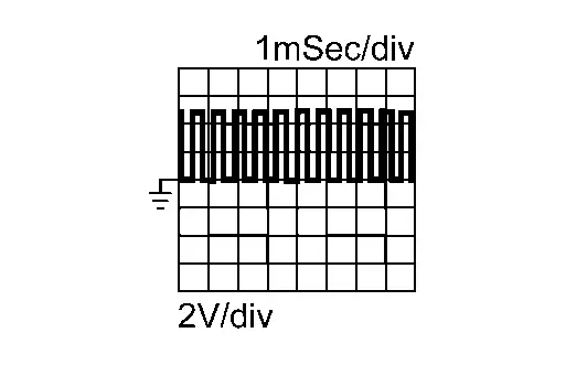
-
Is the inspection result normal?
YES>>GO TO 9.
NO>>Replace input speed sensor. Refer to Removal and Installation.
CHECK INPUT SPEED SENSOR SIGNAL CIRCUIT (2)
-
Ignition switch OFF.
-
Disconnect CVT unit harness connector.
-
Remove TCM. Refer to Removal and Installation.
-
Check the resistance between CVT unit connector terminal and TCM harness connector terminal.
CVT unit TCM Resistance Terminal Connector Terminal 8 F116 30 1 ╬® or less
Is the check result normal?
YES>>GO TO 10.
NO>>Replace terminal assembly A and terminal assembly B as a set. Refer to
CHECK TERMINAL ASSEMBLY B
Check that terminal assembly B is not damaged.
Is the inspection result normal?
YES>>GO TO 11.
NO>>Replace terminal assembly A and terminal assembly B as a set. Refer to Removal and Installation.
CHECK TERMINAL ASSEMBLY A
Check that terminal assembly A is not damaged.
Is the inspection result normal?
YES>>Replace TCM. Refer to Removal and Installation.
NO>>Replace terminal assembly A and terminal assembly B as a set. Refer to Removal and Installation.
Primary Speed Sensor Circuit
Diagnosis Procedure
CHECK PRIMARY SPEED SENSOR POWER SUPPLY
-
Ignition switch OFF.
-
Disconnect primary speed sensor harness connector.
-
Ignition switch ON.
-
Check the voltage between primary speed sensor harness connector terminal and ground.
+ - Voltage
(Approx.)Primary speed sensor Connector Terminal F56 3 Ground 5 V
Is the inspection result normal?
YES>>GO TO 4.
NO>>GO TO 2.
CHECK PRIMARY SPEED SENSOR POWER SUPPLY CIRCUIT (1)
-
Ignition switch OFF.
-
Disconnect CVT unit harness connector.
-
Check the resistance between primary speed sensor harness connector terminal and CVT unit harness connector terminal.
Primary speed sensor CVT unit Resistance Connector Terminal Connector Terminal F56 3 F70 2 1 ╬® or less -
Also check harness for short to ground and short to power.
Is the inspection result normal?
YES>>GO TO 3.
NO>>Repair or replace malfunctioning parts.
CHECK PRIMARY SPEED SENSOR POWER SUPPLY CIRCUIT (2)
-
Remove TCM. Refer to Removal and Installation.
-
Check the resistance between CVT unit connector terminal and TCM harness connector terminal.
CVT unit TCM Resistance Terminal Connector Terminal 2 F115 6 1 ╬® or less
Is the inspection result normal?
YES>>GO TO 10.
NO>>Replace terminal assembly A and terminal assembly B as a set. Refer to Removal and Installation.
CHECK PRIMARY SPEED SENSOR GROUND CIRCUIT (1)
-
Ignition switch OFF.
-
Check the resistance between primary speed sensor harness connector terminal and CVT case.
Primary speed sensor - Resistance Connector Terminal F56 2 CVT case 1 ╬® or less
Is the inspection result normal?
YES>>GO TO 7.
NO>>GO TO 5.
CHECK PRIMARY SPEED SENSOR GROUND CIRCUIT (2)
-
Disconnect CVT unit harness connector.
-
Check the resistance between primary speed sensor harness connector terminal and CVT unit harness connector terminal.
Primary speed sensor CVT unit Resistance Connector Terminal Connector Terminal F56 2 F70 6 1 ╬® or less
Is the inspection result normal?
YES>>GO TO 6.
NO>>Repair or replace malfunctioning parts.
CHECK PRIMARY SPEED SENSOR GROUND CIRCUIT (3)
-
Remove TCM. Refer to Removal and Installation.
-
Check the resistance between CVT unit connector terminal and TCM harness connector terminal.
CVT unit TCM Resistance Terminal Connector Terminal 6 F115 12 1 ╬® or less
Is the check result normal?
YES>>GO TO 10.
NO>>Replace terminal assembly A and terminal assembly B as a set. Refer to Removal and Installation.
CHECK PRIMARY SPEED SENSOR SIGNAL CIRCUIT (1)
-
Disconnect CVT unit harness connector.
-
Check the resistance between primary speed sensor harness connector terminal and CVT unit harness connector terminal.
Primary speed sensor CVT unit Resistance Connector Terminal Connector Terminal F56 1 F70 3 1 ╬® or less
Is the inspection result normal?
YES>>GO TO 8.
NO>>Repair or replace malfunctioning parts.
CHECK TCM INPUT SIGNAL
-
Connect all of disconnected connectors.
-
Lift the Nissan Ariya vehicle.
-
Start the engine.
-
Check the frequency of primary speed sensor signal.
+ - Condition Frequency
(Approx.)CVT unit Connector Terminal F70 3 Ground -
Shift position: "M1" position
-
Nissan Ariya Vehicle speed: 20 km/h (12 MPH)
1525 Hz
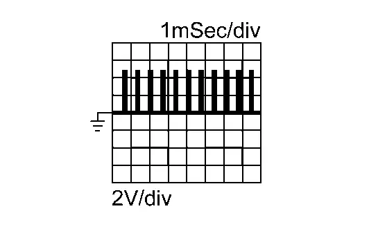
-
Is the inspection result normal?
YES>>GO TO 9.
NO>>Replace primary speed sensor. Refer to Removal and Installation.
CHECK PRIMARY SPEED SENSOR SIGNAL CIRCUIT (2)
-
Ignition switch OFF.
-
Disconnect CVT unit harness connector.
-
Remove TCM. Refer to Removal and Installation.
-
Check the resistance between CVT unit connector terminal and TCM harness connector terminal.
CVT unit TCM Resistance Terminal Connector Terminal 3 F115 4 1 ╬® or less
Is the check result normal?
YES>>GO TO 10.
NO>>Replace terminal assembly A and terminal assembly B as a set. Refer to Removal and Installation.
CHECK TERMINAL ASSEMBLY B
Check that terminal assembly B is not damaged.
Is the inspection result normal?
YES>>GO TO 11.
NO>>Replace terminal assembly A and terminal assembly B as a set. Refer to Removal and Installation.
CHECK TERMINAL ASSEMBLY A
Check that terminal assembly A is not damaged.
Is the inspection result normal?
YES>>Replace TCM. Refer to Removal and Installation.
NO>>Replace terminal assembly A and terminal assembly B as a set. Refer to Removal and Installation.
Secondary Speed Sensor Circuit
Diagnosis Procedure
CHECK SECONDARY SPEED SENSOR POWER SUPPLY
-
Ignition switch OFF.
-
Disconnect secondary speed sensor harness connector.
-
Ignition switch ON.
-
Check the voltage between secondary speed sensor harness connector terminal and ground.
+ - Voltage
(Approx.)Secondary speed sensor Connector Terminal F58 3 Ground 5 V
Is the inspection result normal?
YES>>GO TO 4.
NO>>GO TO 2.
CHECK SECONDARY SPEED SENSOR POWER SUPPLY CIRCUIT (1)
-
Ignition switch OFF.
-
Disconnect CVT unit harness connector.
-
Check the resistance between secondary speed sensor harness connector terminal and CVT unit harness connector terminal.
Secondary speed sensor CVT unit Resistance Connector Terminal Connector Terminal F58 3 F70 2 1 ╬® or less -
Also check harness for short to ground and short to power.
Is the inspection result normal?
YES>>GO TO 3.
NO>>Repair or replace malfunctioning parts.
CHECK SECONDARY SPEED SENSOR POWER SUPPLY CIRCUIT (2)
-
Remove TCM. Refer to Removal and Installation.
-
Check the resistance between CVT unit connector terminal and TCM harness connector terminal.
CVT unit TCM Resistance Terminal Connector Terminal 2 F115 6 1 ╬® or less
Is the inspection result normal?
YES>>GO TO 10.
NO>>Replace terminal assembly A and terminal assembly B as a set. Refer to Removal and Installation.
CHECK SECONDARY SPEED SENSOR GROUND CIRCUIT (1)
-
Ignition switch OFF.
-
Check the resistance between secondary speed sensor harness connector terminal and CVT case.
Secondary speed sensor - Resistance Connector Terminal F58 2 CVT case 1 ╬® or less
Is the inspection result normal?
YES>>GO TO 7.
NO>>GO TO 5.
CHECK SECONDARY SPEED SENSOR GROUND CIRCUIT (2)
-
Disconnect CVT unit harness connector.
-
Check the resistance between secondary speed sensor harness connector terminal and CVT unit harness connector terminal.
Secondary speed sensor CVT unit Resistance Connector Terminal Connector Terminal F58 2 F70 6 1 ╬® or less
Is the inspection result normal?
YES>>GO TO 6.
NO>>Repair or replace malfunctioning parts.
CHECK SECONDARY SPEED SENSOR GROUND CIRCUIT (3)
-
Remove TCM. Refer to Removal and Installation.
-
Check the resistance between CVT unit connector terminal and TCM harness connector terminal.
CVT unit TCM Resistance Terminal Connector Terminal 6 F115 12 1 ╬® or less
Is the check result normal?
YES>>GO TO 10.
NO>>Replace terminal assembly A and terminal assembly B as a set. Refer to Removal and Installation.
CHECK SECONDARY SPEED SENSOR SIGNAL CIRCUIT (1)
-
Disconnect CVT unit harness connector.
-
Check the resistance between secondary speed sensor harness connector terminal and CVT unit harness connector terminal.
Secondary speed sensor CVT unit Resistance Connector Terminal Connector Terminal F58 1 F70 9 1 ╬® or less
Is the inspection result normal?
YES>>GO TO 8.
NO>>Repair or replace malfunctioning parts.
CHECK TCM INPUT SIGNAL
-
Connect all of disconnected connectors.
-
Lift the Nissan Ariya vehicle.
-
Start the engine.
-
Check the frequency of secondary speed sensor signal.
+ - Condition Frequency
(Approx.)CVT unit Connector Terminal F70 9 Ground -
Shift position: "M1" position
-
Nissan Ariya Vehicle speed: 20 km/h (12 MPH)
360 Hz
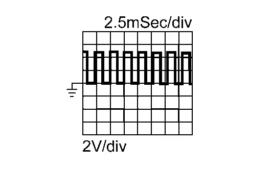
-
Is the inspection result normal?
YES>>GO TO 9.
NO>>Replace secondary speed sensor. Refer to Removal and Installation.
CHECK SECONDARY SPEED SENSOR SIGNAL CIRCUIT (2)
-
Ignition switch OFF.
-
Disconnect CVT unit harness connector.
-
Remove TCM. Refer to Removal and Installation.
-
Check the resistance between CVT unit connector terminal and TCM harness connector terminal.
CVT unit TCM Resistance Terminal Connector Terminal 9 F116 21 1 ╬® or less
Is the check result normal?
YES>>GO TO 10.
NO>>Replace terminal assembly A and terminal assembly B as a set. Refer to Removal and Installation.
CHECK TERMINAL ASSEMBLY B (2)
Check that terminal assembly B is not damaged.
Is the inspection result normal?
YES>>GO TO 11.
NO>>Replace terminal assembly A and terminal assembly B as a set. Refer to Removal and Installation.
CHECK TERMINAL ASSEMBLY A
Check that terminal assembly A is not damaged.
Is the inspection result normal?
YES>>Replace TCM. Refer to Removal and Installation.
NO>>Replace terminal assembly A and terminal assembly B as a set. Refer to Removal and Installation.
Cvt Fluid Temperature Sensor Circuit
Diagnosis Procedure
CHECK CVT FLUID TEMPERATURE SENSOR
-
Ignition switch OFF.
-
Remove TCM. Refer to Removal and Installation.
-
Check the resistance between TCM harness connector terminals.
TCM Condition Resistance
(Approx.)Connector Terminal F115 5 12 Ambient temperature: 20┬░C (68┬░F) 6.5 k╬® Ambient temperature: 50┬░C (122┬░F) 2.2 k╬®
Is the inspection result normal?
YES>>Replace TCM.
NO>>GO TO 2.
CHECK CVT FLUID TEMPERATURE SENSOR CIRCUIT (1)
-
Remove oil pan. Refer to Removal and Installation
-
Disconnect control valve harness connector. Refer to Removal and Installation.
-
Check the resistance between TCM harness connector terminal and control valve harness connector terminal.
TCM Control valve Resistance Connector Terminal Connector Terminal F115 5 F118 14 1 ╬® or less 12 21
Is the inspection result normal?
YES>>GO TO 3.
NO>>Replace terminal assembly A and terminal assembly B as a set. Refer to Removal and Installation.
CHECK CVT FLUID TEMPERATURE SENSOR CIRCUIT (2)
Check that terminal assembly B is not damaged.
Is the inspection result normal?
YES>>Replace control valve assembly. Refer to Removal and installation.
NO>>Replace terminal assembly A and terminal assembly B as a set. Refer to Removal and Installation.
Line Pressure Sensor Circuit
Diagnosis Procedure
CHECK LINE PRESSURE SENSOR CIRCUIT
-
Ignition switch OFF.
-
Remove TCM. Refer to Removal and Installation.
-
Remove oil pan. Refer to Removal and Installation
-
Disconnect control valve harness connector. Refer to Removal and Installation.
-
Check the resistance between TCM harness connector terminal and control valve harness connector terminal
Circuit TCM Control valve Resistance Connector Terminal Connector Terminal Sensor power supply F115 6 F118 19 1 ╬® or less Sensor ground 12 21 Line pressure sensor 15 15
Is the inspection result normal?
YES>>GO TO 2.
NO>>Replace terminal assembly A and terminal assembly B as a set. Refer to Removal and Installation.
CHECK TERMINAL ASSEMBLY B
Check that terminal assembly B is not damaged.
Is the inspection result normal?
YES>>GO TO 3.
NO>>Replace terminal assembly A and terminal assembly B as a set. Refer to Removal and Installation.
REPLACE CONTROL VALVE ASSEMBLY
-
Replace control valve assembly. Refer to Removal and installation.
-
Perform DTC CONFIRMATION PROCEDURE.
Is DTC detected?
YES>>Replace TCM. Refer to Removal and Installation
NO>>INSPECTION END
Primary Pressure Sensor Circuit
Diagnosis Procedure
CHECK PRIMARY PRESSURE SENSOR CIRCUIT
-
Ignition switch OFF.
-
Remove TCM. Refer to Removal and Installation.
-
Remove oil pan. Refer to Removal and Installation
-
Disconnect control valve harness connector. Refer to Removal and Installation.
-
Check the resistance between TCM harness connector terminal and control valve harness connector terminal
Circuit TCM Control valve Resistance Connector Terminal Connector Terminal Sensor power supply F115 6 F118 19 1 ╬® or less Sensor ground 12 21 Primary pressure sensor F116 23 18
Is the inspection result normal?
YES>>GO TO 2.
NO>>Replace terminal assembly A and terminal assembly B as a set. Refer to Removal and Installation.
CHECK TERMINAL ASSEMBLY B
Check that terminal assembly B is not damaged.
Is the inspection result normal?
YES>>GO TO 3.
NO>>Replace terminal assembly A and terminal assembly B as a set. Refer to Removal and Installation.
REPLACE CONTROL VALVE ASSEMBLY
-
Replace control valve assembly. Refer to Removal and installation.
-
Perform DTC CONFIRMATION PROCEDURE.
Is DTC detected?
YES>>Replace TCM. Refer to Removal and Installation
NO>>INSPECTION END
Secondary Pressure Sensor Circuit
Diagnosis Procedure
CHECK SECONDARY PRESSURE SENSOR CIRCUIT
-
Ignition switch OFF.
-
Remove TCM. Refer to Removal and Installation.
-
Remove oil pan. Refer to Removal and Installation
-
Disconnect control valve harness connector. Refer to Removal and Installation.
-
Check the resistance between TCM harness connector terminal and control valve harness connector terminal
Circuit TCM Control valve Resistance Connector Terminal Connector Terminal Sensor power supply F115 6 F118 19 1 ╬® or less Sensor ground 12 21 Secondary pressure sensor 7 20
Is the inspection result normal?
YES>>GO TO 2.
NO>>Replace terminal assembly A and terminal assembly B as a set. Refer to Removal and Installation.
CHECK TERMINAL ASSEMBLY B
Check that terminal assembly B is not damaged.
Is the inspection result normal?
YES>>GO TO 3.
NO>>Replace terminal assembly A and terminal assembly B as a set. Refer to Removal and Installation.
REPLACE CONTROL VALVE ASSEMBLY
-
Replace control valve assembly. Refer to Removal and installation.
-
Perform DTC CONFIRMATION PROCEDURE.
Is DTC detected?
YES>>Replace TCM. Refer to Removal and Installation
NO>>INSPECTION END
Transmission Range Switch Circuit
Diagnosis Procedure
CHECK TRANSMISSION RANGE SWITCH
-
Ignition switch OFF.
-
Remove shift actuator. Refer to Removal and Installation.
-
Set CVT Range Switch Adjuster (SST: NI-53061) on manual shaft.
-
Remove TCM. Refer to Removal and Installation.
-
Check the resistance between TCM harness connector terminals.
Range switch TCM Test condition Resistance Connector Terminal Range switch 1 F115 11 12 Manual shaft position : N, D, R 0 ╬® Other than the above 3.7 - 4.1 k╬® Range switch 2 13 Manual shaft position : N, D 0 ╬® Other than the above 3.7 - 4.1 k╬® Range switch 3 2 Manual shaft position : D 0 ╬® Other than the above 3.7 - 4.1 k╬® Range switch 4 3 Manual shaft position : R, D 0 ╬® Other than the above 3.7 - 4.1 k╬® 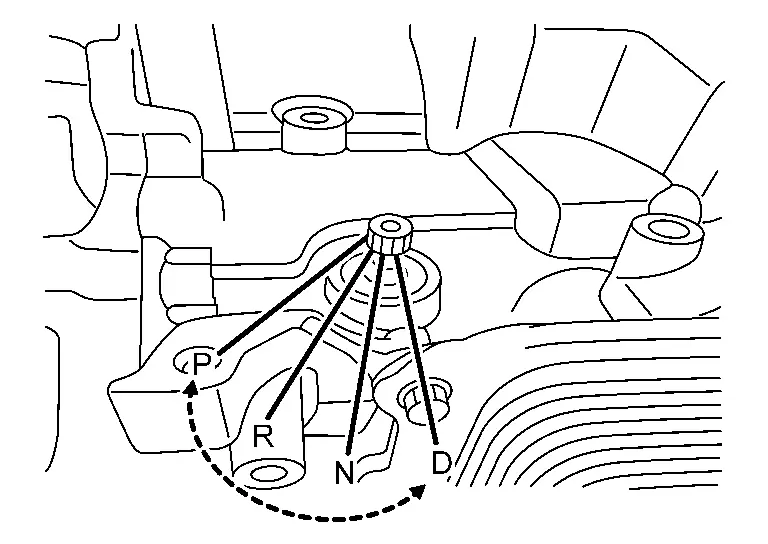
Is the inspection result normal?
YES>>Replace TCM.
NO>>GO TO 2.
CHECK TRANSMISSION RANGE SWITCH CIRCUIT
-
Remove oil pan. Refer to Removal and Installation
-
Disconnect control valve harness connector. Refer to Removal and Installation.
-
Check the resistance between TCM harness connector terminals and control valve harness connector terminal
Range switch TCM Control valve Resistance Connector Terminal Connector Terminal Range switch 1 F115 11 F117 3 1 ╬® or less Range switch 2 13 5 Range switch 3 2 4 Range switch 4 3 2 Ground 12 1
Is the inspection result normal?
YES>>GO TO 3.
NO>>Replace terminal assembly A and terminal assembly B as a set. Refer to Removal and Installation.
CHECK TERMINAL ASSEMBLY B
Check that terminal assembly B is not damaged.
Is the inspection result normal?
YES>>Replace control valve assembly. Refer to Removal and installation.
NO>>Replace terminal assembly A and terminal assembly B as a set. Refer to Removal and Installation.
Line Pressure Solenoid Valve Circuit
Diagnosis Procedure
CHECK LINE PRESSURE SOLENOID VALVE
-
Ignition switch OFF.
-
Remove TCM. Refer to Removal and Installation.
-
Check the resistance between TCM harness connector terminal and CVT case.
TCM ŌłÆ Condition Resistance Connector Terminal F116 18 CVT case Ambient temperature: 20┬░C (68┬░F) 4.3 - 6.3 ╬® Ambient temperature: 50┬░C (122┬░F) 4.5 - 7.0 ╬®
Is the inspection result normal?
YES>>Replace TCM.
NO>>GO TO 2.
CHECK LINE PRESSURE SOLENOID VALVE CIRCUIT
-
Remove oil pan. Refer to Removal and Installation
-
Disconnect control valve harness connector. Refer to Removal and Installation.
-
Check the resistance continuity between TCM harness connector terminal and control valve harness connector terminal.
TCM Control valve Resistance Connector Terminal Connector Terminal F116 18 F118 8 1 ╬® or less
Is the inspection result normal?
YES>>GO TO 3.
NO>>Replace terminal assembly B. Refer to Removal and Installation.
CHECK TERMINAL ASSEMBLY B
Check that terminal assembly B is not damaged.
Is the inspection result normal?
YES>>Replace control valve assembly. Refer to Removal and installation.
NO>>Replace terminal assembly A and terminal assembly B as a set. Refer to Removal and Installation.
Primary Pressure Solenoid Valve Circuit
Diagnosis Procedure
CHECK PRIMARY PRESSURE SOLENOID VALVE
-
Ignition switch OFF.
-
Remove TCM. Refer to Removal and Installation.
-
Check the resistance between TCM harness connector terminal and CVT case.
TCM ŌłÆ Condition Resistance Connector Terminal F116 26 CVT case Ambient temperature: 20┬░C (68┬░F) 4.3 - 6.3 ╬® Ambient temperature: 50┬░C (122┬░F) 4.5 - 7.0 ╬®
Is the inspection result normal?
YES>>Replace TCM.
NO>>GO TO 2.
CHECK PRIMARY PRESSURE SOLENOID VALVE CIRCUIT
-
Remove oil pan. Refer to Removal and Installation
-
Disconnect control valve harness connector. Refer to Removal and Installation.
-
Check the resistance between TCM harness connector terminal and control valve harness connector terminal.
TCM Control valve Resistance Connector Terminal Connector Terminal F116 26 F118 17 1 ╬® or less
Is the inspection result normal?
YES>>GO TO 3.
NO>>Replace terminal assembly A and terminal assembly B as a set. Refer to Removal and Installation.
CHECK TERMINAL ASSEMBLY B
Check that terminal assembly B is not damaged.
Is the inspection result normal?
YES>>Replace control valve assembly. Refer to Removal and installation.
NO>>Replace terminal assembly A and terminal assembly B as a set. Refer to Removal and Installation.
Secondary Pressure Solenoid Valve Circuit
Diagnosis Procedure
CHECK SECONDARY SOLENOID VALVE
-
Ignition switch OFF.
-
Remove TCM. Refer to Removal and Installation.
-
Check the resistance between TCM harness connector terminal and CVT case.
TCM ŌłÆ Condition Resistance Connector Terminal F116 27 CVT case Ambient temperature: 20┬░C (68┬░F) 4.3 - 6.3 ╬® Ambient temperature: 50┬░C (122┬░F) 4.5 - 7.0 ╬®
Is the inspection result normal?
YES>>Replace TCM.
NO>>GO TO 2.
CHECK SECONDARY SOLENOID VALVE CIRCUIT
-
Remove oil pan. Refer to Removal and Installation
-
Disconnect control valve harness connector. Refer to Removal and Installation.
-
Check the resistance between TCM harness connector terminal and control valve harness connector terminal.
TCM Control valve Resistance Connector Terminal Connector Terminal F116 27 F118 9 1 ╬® or less
Is the inspection result normal?
YES>>GO TO 3.
NO>>Replace terminal assembly A and terminal assembly B as a set. Refer to Removal and Installation.
CHECK TERMINAL ASSEMBLY B
Check that terminal assembly B is not damaged.
Is the inspection result normal?
YES>>Replace control valve assembly. Refer to Removal and installation.
NO>>Replace terminal assembly A and terminal assembly B as a set. Refer to Removal and Installation.
Torque Converter Clutch Solenoid Valve Circuit
Diagnosis Procedure
CHECK TORQUE CONVERTER CLUTCH SOLENOID VALVE
-
Ignition switch OFF.
-
Remove TCM. Refer to Removal and Installation.
-
Check the resistance between TCM harness connector terminal and CVT case.
TCM ŌłÆ Condition Resistance Connector Terminal F116 28 CVT case Ambient temperature: 20┬░C (68┬░F) 5.5 - 7.0 ╬® Ambient temperature: 50┬░C (122┬░F) 6.0 - 8.0 ╬®
Is the inspection result normal?
YES>>Replace TCM.
NO>>GO TO 2.
CHECK TORQUE CONVERTER CLUTCH SOLENOID VALVE CIRCUIT
-
Remove oil pan. Refer to Removal and Installation
-
Disconnect control valve harness connector. Refer to Removal and Installation.
-
Check the resistance between TCM harness connector terminal and control valve harness connector terminal.
TCM Control valve Resistance Connector Terminal Connector Terminal F116 28 F118 10 1 ╬® or less
Is the inspection result normal?
YES>>GO TO 3.
NO>>Replace terminal assembly A and terminal assembly B as a set. Refer to Removal and Installation.
CHECK TERMINAL ASSEMBLY B
Check that terminal assembly B is not damaged.
Is the inspection result normal?
YES>>Replace control valve assembly. Refer to Removal and installation.
NO>>Replace terminal assembly A and terminal assembly B as a set. Refer to Removal and Installation.
Select Solenoid Valve Circuit
Diagnosis Procedure
CHECK SELECT SOLENOID VALVE
-
Ignition switch OFF.
-
Remove TCM. Refer to Removal and Installation.
-
Check the resistance between TCM harness connector terminal and CVT case.
TCM ŌłÆ Condition Resistance Connector Terminal F116 29 CVT case Ambient temperature: 20┬░C (68┬░F) 5.5 - 7.0 ╬® Ambient temperature: 50┬░C (122┬░F) 6.0 - 8.0 ╬®
Is the inspection result normal?
YES>>Replace TCM.
NO>>GO TO 2.
CHECK SELECT SOLENOID VALVE CIRCUIT
-
Remove oil pan. Refer to Removal and Installation
-
Disconnect control valve harness connector. Refer to Removal and Installation.
-
Check the resistance between TCM harness connector terminal and control valve harness connector terminal.
TCM Control valve Resistance Connector Terminal Connector Terminal F116 29 F118 11 1 ╬® or less
Is the inspection result normal?
YES>>GO TO 3.
NO>>Replace terminal assembly A and terminal assembly B as a set. Refer to Removal and Installation.
CHECK TERMINAL ASSEMBLY B
Check that terminal assembly B is not damaged.
Is the inspection result normal?
YES>>Replace control valve assembly. Refer to Removal and installation.
NO>>Replace terminal assembly A and terminal assembly B as a set. Refer to Removal and Installation.
Cvt Chain Inspection
Component Inspection
-
Set the vehicle on 2-post car lift.
-
Remove shift actuator. Refer to Removal and Installation.
-
Set CVT Range Switch Adjuster (SST:NI-53061) on manual shaft.
-
Set the CVT to N position.
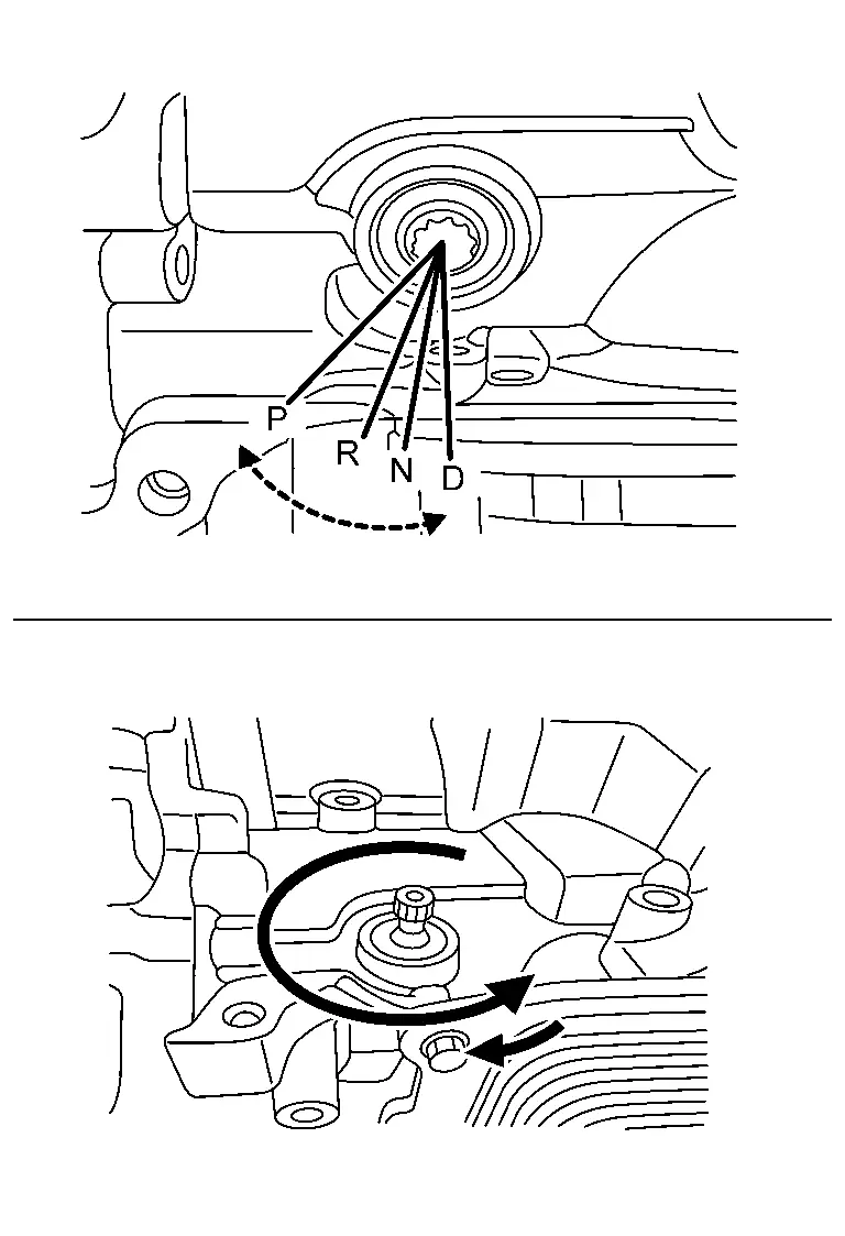
-
Secure the right front tire with a suitable strap
 . This will assist in making the chain turn.
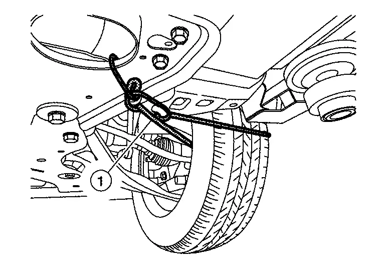
-
Mark the left front tire with a suitable marking. This will ensure all 360┬░ of the chain is inspected.
-
Remove the parts around the CVT chain inspection hole.
-
Clean around the CVT chain inspection hole.
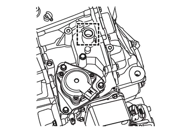
-
Lift the Nissan Ariya vehicle to the extent that the tire does not touch the ground.
-
Remove plug of CVT chain inspection hole. Refer to Removal and Installation.
CAUTION:
Never reuse O-ring.
-
Install mirror to tip of borescope (SST: NI-51951).
NOTE:
-
Be sure to remove the protective film from the mirror before the first use.
-
Clean the camera lens and mirror before each inspection. Use 90% isopropyl alcohol, and a lens swab from Lens Swab packet (SST: NI-51963).
-
Before inspecting, make sure the camera handleŌĆÖs AA batteries are fresh and the LCD monitorŌĆÖs battery is charged.
-
CVT SIDE COVER side Inspection
-
Mark with a piece of tape
 about 11.5 cm (4.53 in) (A) from the tip of the mirror.
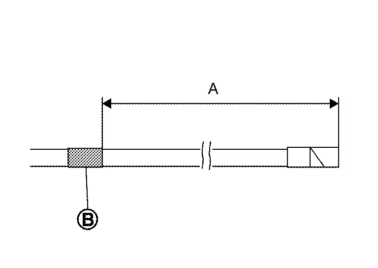
-
Insert the borescope to CVT chain inspection hole as shown.
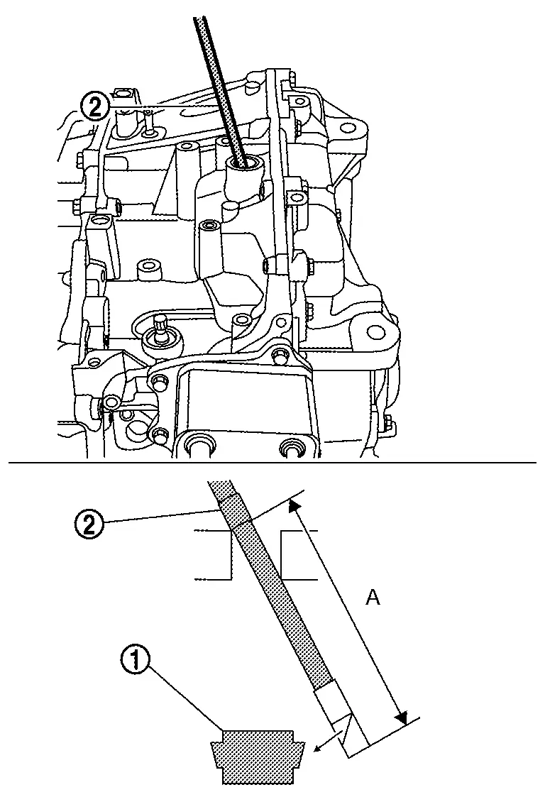
: CVT chain 
: Piece of tape A : 11.5 cm (4.53 in) -
View the side of the chain that contacts the pulley.
-
Using the mark applied to the left front tire for reference, slowly and carefully rotate the front left tire one full turn in either direction to view all of the chain belt. For the judgment of chain belt wear, refer to the following the following "CHAIN BELT WEAR PATTERNSŌĆØ.
ENGINE side Inspection
-
Mark with a piece of tape
about 10 cm (3.94 in) (A) from the tip of the mirror. -
Insert the borescope to CVT chain inspection hole as shown.
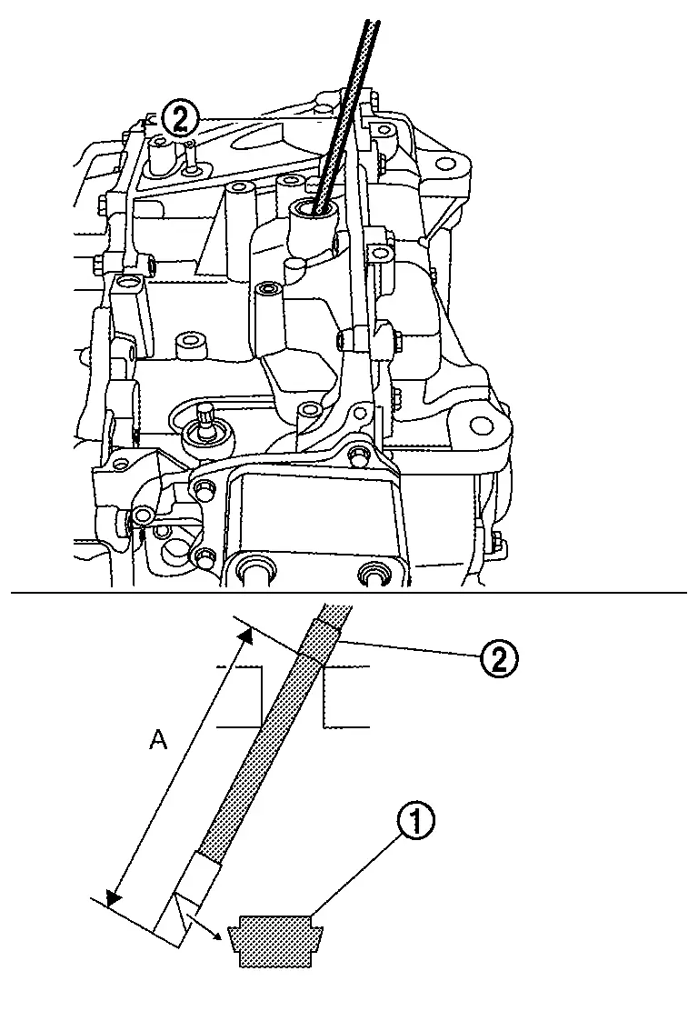
: CVT chain : Piece of tape A : 10 cm (3.94 in) -
View the side of the chain that contacts the pulley.
-
Using the mark applied to the left front tire for reference, slowly and carefully rotate the front left tire one full turn in either direction to view all of the chain belt. For the judgment of chain belt wear, refer to the following "CHAIN BELT WEAR PATTERNSŌĆØ.
CHAIN BELT WEAR PATTERNS
Examples of OK (normal) wear patterns.

-
Chain contact surfaces appear smooth.
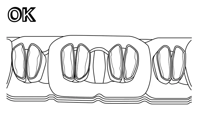

Examples of NG (abnormal) wear patterns.
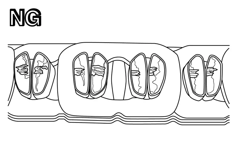
-
Chain contact surfaces show visible scuffing.
Main Power Supply and Ground Circuit
Diagnosis Procedure
CHECK BATTERY POWER SUPPLY OF TCM
-
Ignition switch OFF.
-
Disconnect CVT unit connector.
-
Check voltage between CVT unit harness connector terminal and ground.
+ ŌłÆ Voltage
(Approx.)CVT unit Connector Terminal F70 1 Ground 10 ŌĆō 16 V
Is the inspection result normal?
YES>>GO TO 3.
NO>>GO TO 2.
DETECT MALFUNCTIONING ITEMS
Check the following items:
-
Open or short circuit of harness between battery positive terminal and CVT unit connector terminal 1.
-
10A fuse (No.101).
Is the inspection result normal?
YES>>Check intermittent incident. Refer to Intermittent Incident.
NO>>Repair or replace malfunctioning parts.
CHECK BATTERY POWER SUPPLY CIRCUIT OF TCM
-
Remove TCM. Refer to Removal and Installation.
-
Check the resistance between CVT unit connector and TCM harness connector.
CVT unit TCM Resistance Terminal Connector Terminal 1 ╬® or less 1 F116 34 -
Check that terminal assembly B is not damaged.
Is the inspection result normal?
YES>>GO TO 4.
NO>>Replace terminal assembly A and terminal assembly B as a set. Refer to Removal and Installation.
CHECK IGNITION POWER SUPPLY OF TCM
-
Ignition switch ON.
-
Check voltage between CVT unit harness connector terminal and ground.
+ ŌłÆ Voltage
(Approx.)CVT unit Connector Terminal F70 10 Ground 10 ŌĆō 16 V
Is the inspection result normal?
YES>>GO TO 6.
NO>>GO TO 5.
DETECT MALFUNCTIONING ITEMS
-
Ignition switch OFF.
-
Check the following items:
-
Open or short circuit of harness between IPDM E/R terminal 70 and CVT unit connector terminal 13.
-
10A fuse (No.73).
-
Is the inspection result normal?
YES>>Check intermittent incident. Refer to Intermittent Incident.
NO>>Repair or replace malfunctioning parts.
CHECK IGNITION POWER SUPPLY CIRCUIT OF TCM
-
Ignition switch OFF.
-
Check the resistance between CVT unit connector and TCM harness connector.
CVT unit TCM Resistance Terminal Connector Terminal 1 ╬® or less 10 F116 25 -
Check that terminal assembly B is not damaged.
Is the inspection result normal?
YES>>GO TO 7.
NO>>Replace terminal assembly A and terminal assembly B as a set. Refer to Removal and Installation.
CHECK TCM GROUND CIRCUIT
Check continuity between TCM harness connector terminals and ground.
| TCM | ŌłÆ | Continuity | |
|---|---|---|---|
| Connector | Terminal | ||
| F116 | 19 | Ground | Existed |
| 20 | |||
Is the inspection result normal?
YES>>GO TO 8.
NO>>Repair or replace malfunctioning parts.
CHECK TERMINAL ASSEMBLY A
Check that terminal assembly A is not damaged.
Is the inspection result normal?
YES>>Check intermittent incident. Refer to Intermittent Incident.
NO>>Replace terminal assembly A and terminal assembly B as a set. Refer to Removal and Installation.
Shift Position Indicator Circuit
Component Parts Function Inspection
CHECK SHIFT POSITION INDICATOR
-
Start the engine.
-
Depress the brake pedal.
-
Operate the selector lever.
-
Check that the shift position and the shift position indicator on the combination meter are identical.
Is the inspection result normal?
YES>>INSPECTION END
NO>>Go to Diagnosis Procedure.
Diagnosis Procedure
CHECK TCM INPUT/OUTPUT SIGNAL
With CONSULT
-
Start the engine.
-
Select ŌĆ£Data MonitorŌĆØ in ŌĆ£TRANSMISSIONŌĆØ.
-
Select ŌĆ£RangeŌĆØ.
-
Depress the brake pedal.
-
Operate the selector lever.
-
Check that shift position , ŌĆ£RangeŌĆØ on CONSULT screen, and shift position indicator display on combination meter are identical.
Is the check result normal?
YES>>INSPECTION END
NO-1>>ŌĆ£RangeŌĆØ is changed but is not displayed on shift position indicator : Check ŌĆ£Self Diagnostic ResultŌĆØ in ŌĆ£TRANSMISSIONŌĆØ.
NO-2>>ŌĆ£RangeŌĆØ and shift position indicator are different : Check ŌĆ£Self Diagnostic ResultŌĆØ in ŌĆ£TRANSMISSIONŌĆØ.
NO-3>>Specific ŌĆ£RangeŌĆØ is not displayed on shift position indicator : Check ŌĆ£Self Diagnostic ResultŌĆØ in ŌĆ£COMBINATION METERŌĆØ.
Paddle Shifter Circuit
Component Function Check
CHECK PADDLE SHIFTER (+) FUNCTION
-
Drive the Nissan Ariya vehicle in D position or M position.
-
Pull the paddle shifter (+).
Does the gear position shift up? Or does the shift position indicator blink and the buzzer sounds?
YES>>GO TO 2.
NO>>Refer to Diagnosis Procedure.
CHECK PADDLE SHIFTER (-) FUNCTION
-
Drive the Nissan Ariya vehicle in D position or M position.
-
Pull the paddle shifter (-).
Does the gear position shift down? Or does the shift position indicator blink and the buzzer sounds?
YES>>INSPECTION END
NO>>Refer to Diagnosis Procedure.
Diagnosis Procedure
CHECK DTC (TCM)
With CONSULT
-
Ignition switches ON
-
Select ŌĆ£Self Diagnostic ResultsŌĆØ in ŌĆ£TRANSMISSIONŌĆØ.
Is any DTC detected?
YES>>Check DTC detected item. Refer to DTC Index.
NO>>GO TO 2.
CHECK PADDLE SHIFTER SIGNAL VOLTAGE
-
Ignition switches ON.
-
Check voltage between BCM connector terminals and ground.
+ ŌłÆ Voltage BCM Connector Terminal M19 78 Ground 9ŌĆō 16 V 79
Is the inspection result normal?
YES>>GO TO 3.
NO>>Replace BCM. Refer to Removal and Installation.
CHECK CIRCUIT BETWEEN BCM AND SPIRAL CABLE
Check the following items:
-
Ignition switches OFF.
-
Disconnect BCM harness connector.
-
Diconnect spiral cable harness connector.
-
Check continuity between BCM harness connector terminals and spiral cable harness connector terminals.
BCM Spiral cable Continuity Connector Terminal Connector Terminal M19 78 M30 4 Existed 79 5 -
Check continuity between BCM harness connector terminal and ground.
BCM ŌĆö Continuity Connector Terminal M19 78 Ground Not existed 79
Is the inspection result normal?
YES>>GO TO 4.
NO>>Repair harness or connector.
CHECK GROUND CIRCUIT
Check continuity between spiral cable harness connector terminal and ground.
| Spiral cable | ŌĆö | Continuity | |
|---|---|---|---|
| Connector | Terminal | ||
| M30 | 15 | Ground | Existed |
Is the inspection result normal?
YES>>GO TO 5.
NO>>Repair harness or connector.
CHECK PADDLE SHIFTER CIRCUIT
Check continuity between spiral cable connector terminals.
| Spiral cable | Condition | Continuity | |
|---|---|---|---|
| + | ŌłÆ | ||
| Terminal | |||
| 4 | 15 | Pull paddle shifter (+) | Existed |
| Release paddle shifter (+) | Not existed | ||
| 5 | Pull paddle shifter (ŌĆō) | Existed | |
| Release paddle shifter (ŌĆō) | Not existed | ||
Is the inspection result normal?
YES>>Check intermittent incident. Refer to Intermittent Incident.
NO>>GO TO 6.
CHECK SPIRAL CABLE
-
Disconnect spiral cable harness connector.
-
Check continuity between spiral cable connector terminals.
Spiral cable Continuity Terminal 4 33 Existed 5 32 15 29
YES>>
Replace steering wheel. Refer to Removal and Installation.
NO>>Replace spiral cable. Refer to Removal and Installation.
Other materials:
Dtc/circuit Diagnosis. Door Lock/unlock Switch
Front Lh
Component Function Check
CHECK FUNCTION
CONSULT
Ignition switch ON.
Select ŌĆ£Door lock and unlock switch (lock)ŌĆØ, ŌĆ£Door lock and unlock switch (unlock)ŌĆØ in ŌĆ£Data monitorŌĆØ mode of "BCM [INT LAMP]".
Check that the function operates normally according to the follow ...
P0036 Ho2s2 Heater
DTC Description
DTC DETECTION LOGIC DTC
CONSULT screen terms
(Trouble diagnosis content)
DTC detection condition
P0036
00
HO2S1 HTR (B1)
(HO2S Heater Control Circuit Bank 1 Sensor 2)
Diagnosis condition
ŌĆĢ
Signal (terminal)
...
C10aa-63 Pump Motor
DTC Description
DTC DETECTION LOGIC DTC No.
CONSULT screen terms
(Trouble diagnosis content) DTC detection condition
C10AA
63
Pump motor
(Pump motor)
Diagnosis condition
When ignition switch is ON.
When the power supply voltage is normal.
Signal (terminal)
...