Nissan Rogue (T33) 2021-Present Service Manual: Tcm
Exploded View
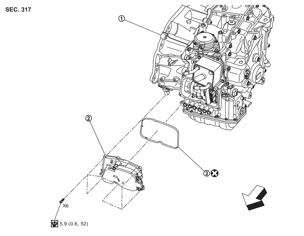
| 1. | Transaxle assembly | 2. | TCM | 3. | gasket |
 : N┬Ęm (kg-m, in-lb)
 : Vehicle front
Removal and Installation
| Never Reuse These Parts | Part Code | For additional information: |
|---|---|---|
| Gasket-TCM | ŌĆō | TCM-Exploded View |
CAUTION:
-
Never impact the TCM when removing or installing TCM.
-
When replacing TCM, perform " ADDITIONAL SERVICE WHEN REPLACING TCM". Refer to Description.
-
When replacing TCM, note the "CVTF DETERIORATION DATE" value displayed on CONSULT "CONFORM CVTF DETERIORATION" in MAINTENANCE BOOKLET, before starting the operation.
REMOVAL
Disconnect the negative battery terminal. Refer to Exploded View.
Drain engine coolant. Refer to Draining.
Remove drain plug from oil pan and then drain the CVT fluid.
Remove air duct and air cleaner. Refer to Exploded View.
Remove engine under cover. Refer to Exploded View.
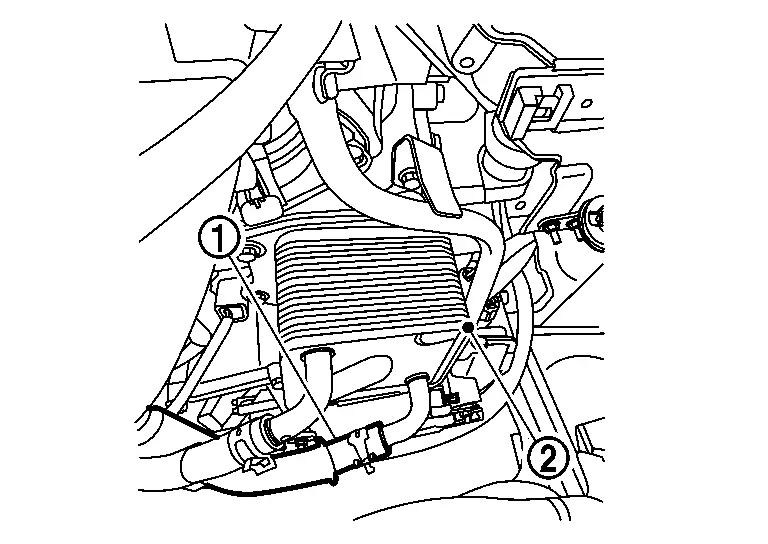
Release CVT water hose clamp (1).
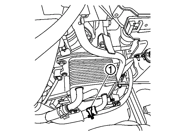
Remove CVT water hose (1) from CVT oil warmer (2).
Remove TCM mounting hexagon bolt (  6 pcs), and then remove TCM (1).
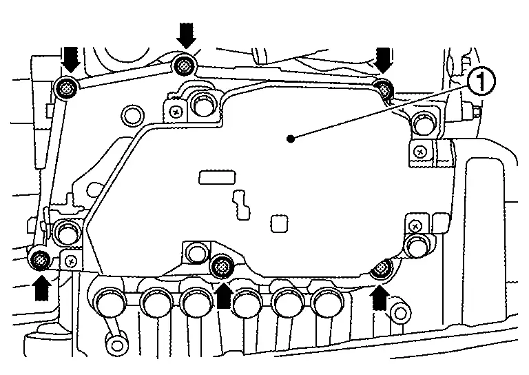
CAUTION:
Never remove any hexagon bolt other than the specified bolts ( 6 pcs).
Remove connectors (A) of terminal assembly B from TCM and then remove TCM from transaxle assembly.
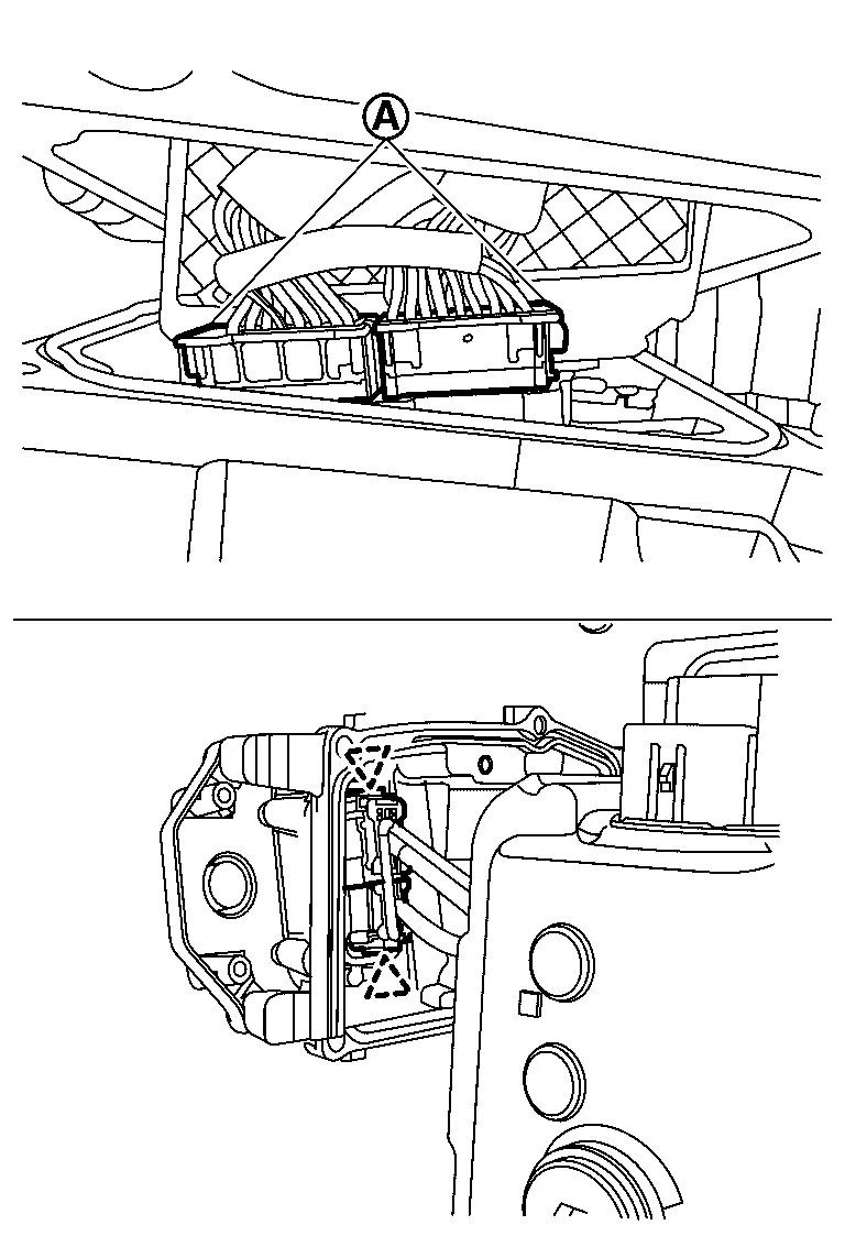
CAUTION:
Never pull the harness forcibly when removing the connectors.
 NOTE:
NOTE:
Terminal assembly B connector claws are located on the upper and lower sides of the connector while connected to the TCM.
Remove gasket (1) from TCM.
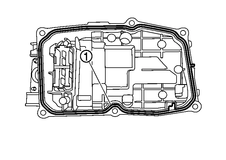
INSTALLATION
-
Install gasket (1) to TCM.
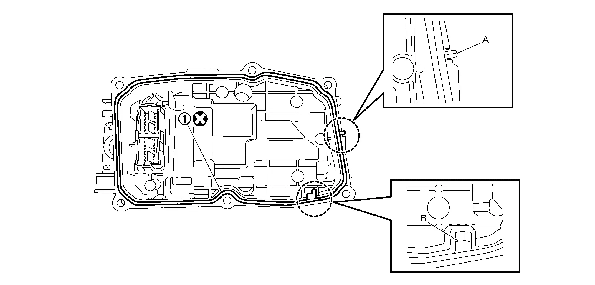
CAUTION:
Never reuse the gasket.
NOTE:
Two tabs (A and B) on TCM gasket need to be set to notches on TCM case.
-
Install connectors (A) of terminal assembly B to TCM.
NOTE:
Terminal assembly B connector claws are located on the upper and lower sides of the connector while connected to the TCM.
-
Tighten TCM mounting hexagon hexagon bolt (
6 pieces) to the specified torque. Refer to Exploded View.1. : TCM CAUTION:
Use appropriate tools to prevent the bolts from tilting.
-
Install CVT water hose from CVT oil warmer and CVT water hose clamps (1).
-
Adjust position of CVT water hose clamps. Refer to Removal and Installation.
-
Install engine under cover. Refer to Exploded View.
-
Install air duct and air cleaner. Refer to Exploded View.
-
Install drain plug from oil pan and then Install the CVT fluid.
-
Install engine coolant. Refer to Refilling.
-
Install the negative battery terminal. Refer to Exploded View.
Adjustment
Perform "ADDITIONAL SERVICE WHEN REPLACING TCM". Refer to Description.
Other materials:
P0036 Ho2s2 Heater
DTC Description
DTC DETECTION LOGIC DTC
CONSULT screen terms
(Trouble diagnosis content)
DTC detection condition
P0036
00
HO2S1 HTR (B1)
(HO2S Heater Control Circuit Bank 1 Sensor 2)
Diagnosis condition
ŌĆĢ
Signal (terminal)
...
Syst├©me temporairement indisponible
Condition A
Dans les conditions suivantes, le t├®moin dŌĆÖavertissement de d├®sactivation du syst├©me de freinage dŌĆÖurgence automatique sŌĆÖallume et le message ┬½ D├®sactiv├® temp. Cam├®ra bloqu├®e ŌĆō Voir manuel du propri├®taire ┬╗ sŌĆÖaffiche sur lŌĆÖ├®cran dŌĆÖinformations du v├®hicule. Le s ...
P06db Engine Oil Pressure Control Solenoid Valve
DTC Description
DTC DETECTION LOGIC DTC
CONSULT screen terms
(Trouble diagnosis content)
DTC detection condition
P06DB
00
ENGINE OIL PRESSURE CONTROL
(Engine oil pressure control circuit low)
Diagnosis condition
ŌĆö
Signal (terminal)
Engine oil pressure control so ...