Nissan Rogue (T33) 2021-Present Service Manual: System Description :: Component Parts. Drive Mode System
Drive Mode System
Component Parts Location

| No. | Component | Function |
|---|---|---|
| 1. | Drive mode select switch | Refer to Drive Mode Select Switch. |
| 2. | Chassis control module |
Chassis control module controls the drive mode select system. Refer to Component Parts Location (without ProPILOT Assist 2.1), or Component Parts Location (with ProPILOT Assist 2.1), for detailed component location. |
| 3. | ABS (Anti-lock Braking System) actuator and electric unit (control unit) |
Receives the drive mode singal from the drime mode switch. Refer to Component Parts Location for detailed component location. |
| 4. | Power steering control module |
Transmits the following signal to the chassis control module via CAN communication:
Receives the following signals from the chassis control module via CAN communication:
|
| 5. | ECM (Engine Control Module) |
Receives the following signal from the chassis control module via CAN communication:
|
| 6. | Electric shift control module |
Receives the following signal from the chassis control module via CAN communication:
|
| 7. | ADAS (Advanced Driver Assistance System) control unit 2 (without ProPILOT assist) |
Receives the following signal from the chassis control module via CAN communication:
|
| 8. | BCM (Body Control Module) |
Transmits the following signal to the chassis control module via CAN communication:
|
| 9. | Comination meter |
Transmits the following signal to the chassis control module via CAN communication:
Receives the following signal from the chassis control module via CAN communication:
|
| 10. | ADAS (Advanced Driver Assistance System) control unit 2 (with ProPILOT assist) |
Receives the following signal from the chassis control module via CAN communication:
|
| 11. | AWD control unit (with AWD system) |
Receives the following signal from the chassis control module via CAN communication:
|
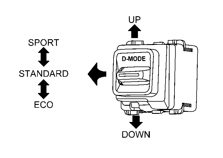
Drive Mode Select Switch
FUNCTIONS WITHIN THE SYSTEM
When drive mode select switch is operated, driving mode is changed for each system.
-
2WD models
-
AWD models

 :
: OFF-ROAD  :
: SNOW  :
: AUTO  :
: ECO  :
: SPORT  :
: hill descent control switch
 NOTE:
NOTE:
For systems that can be changed.
-
2WD Models: Refer to System Description (2WD Models).
-
AWD Models: Refer to System Description (AWD Models).
INDIVIDUAL FUNCTIONS WITHIN THE SYSTEM
Drive mode select switch detected the mode status.
INDIVIDUAL OPERATION
Transmit the drive mode select switch signal to BCM.
PARTS LOCATION
Refer to Component Parts Location.
Other materials:
Cvt: Ge0f14a. Preparation. Preparation
Preparation
Special Service Tools
The actual shape of the tools may differ from those illustrated here.
Tool number
(TechMate No.)
Tool name Description
KV311039S0
(βÄÉβÄîβÄÉ)
Charging pipe set
KV31103920*
(βÄÉβÄîβÄÉ)
O-ring
CVT fluid changing and adjustment
...
Informations de base et fonctionnement
Exemple d'affichage dynamique
LβÄôaffichage tΟΣte haute (Head-Up Display ou HUD) du Nissan Rogue est une technologie de pointe conΟßue pour projeter les donnΟ©es de conduite essentielles directement dans votre champ de vision. Cette innovation permet au conducteur du Nissan Rogue de rester co ...
Front Camera Unit Heater
Component Inspection
CHECK FRONT CAMERA UNIT HEATER
Check the resistance between the front camera unit heater terminals.
Front camera unit heater Resistance [β³Π]
Terminal
1
4
7 βÄ™ 20
Is the inspection result normal?
YES>>
INSPECTION END
NO>>
Replace the fro ...