Nissan Rogue (T33) 2021-Present Service Manual: System Description :: Component Parts. Automatic Drive Positioner
Automatic Drive Positioner
Component Parts Location
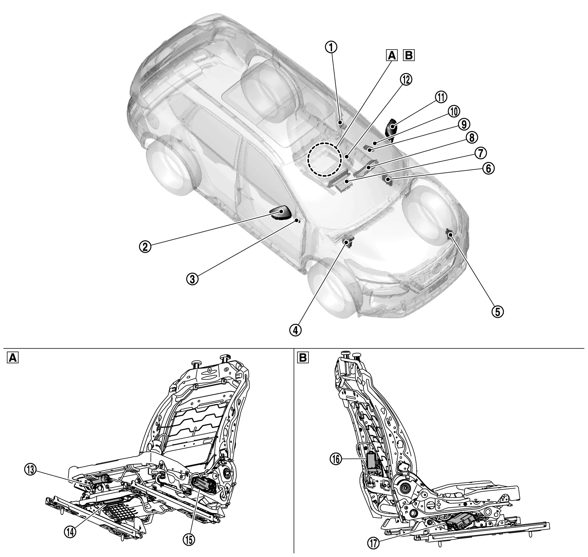
| A. | View with left side of driver seat | B. | View with right side of driver seat |
| No. | Component | Function | ||
|---|---|---|---|---|
| 1. | Front door lock assembly LH (door switch) | Refer to Component Parts Location for detailed component location. | ||
| 2. | Door mirror RH |
|
||
| 3. | Passenger door mirror control module | Refer to Component Parts Location for detailed component location. | ||
| 4. | ABS (Anti-lock Braking System) actuator and electric unit (control unit) | Refer to Component Parts Location for detailed component location. | ||
| 5. | TCM (Transmission Control Module) | Refer to Component Parts Location for detailed component location. | ||
| 6. | BCM (Body Control Module) | Refer to Component Parts Location for detailed component location. | ||
| 7. | AV control unit | Refer to Component Parts Location (with 12.3" color display or Component Parts Location (with 8" color display) for detailed component location. | ||
| 8. | Combination meter | Refer to Component Parts Location (with type A meter) or Component Parts Location (with type B meter) for detailed component location. | ||
| 9. | Power window main switch (door mirror remote control switch) | Refer to Component Parts Location for detailed component location. | ||
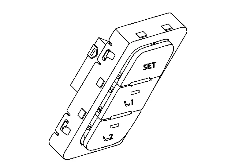
| 10. | Seat memory switch | Refer to Seat Memory Switch. | ||
| 11. | Door mirror LH |
|
||
| 12. | Power seat switch LH | Sliding switch |
|
|
| Reclining switch |
|
|||
| Lifting switch (front) |
|
|||
| Lifting switch (rear) |
|
|||
| 13. | Thigh support motor LH | Refer to System Description. | ||
| 14. | Sliding motor LH |
|
||
| 15. | Lifting motor LH |
|
||
| 16. | Reclining motor LH |
|
||
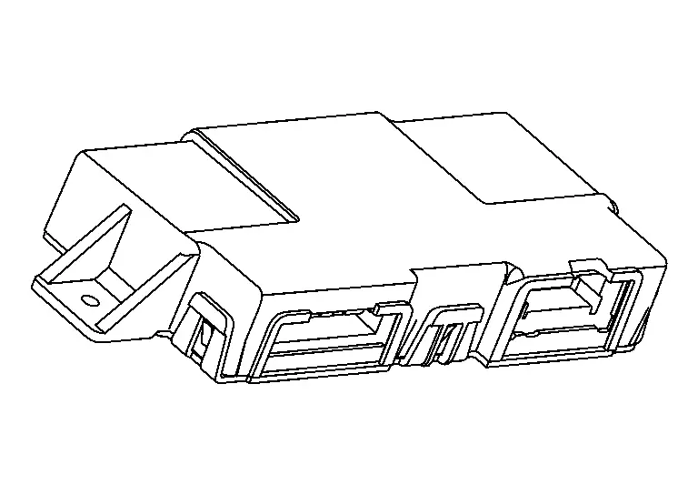
| 17. | Driver seat control unit | Refer to Driver Seat Control Unit. | ||
Driver Seat Control Unit
-
Driver seat control unit is installed in back side of seat cushion. Refer to Component Parts Location for detailed component location.
-
Driver seat control unit is the main unit of automatic drive positioner system.
-
Driver seat control unit controls manual, memory, entry/exit assist, log-in (with navigation system) and Intelligent Key inter lock functions of the automatic drive positioner system.
-
Driver seat control unit communicates with the necessary control units via CAN communication and receives / transmits the required signals to control the system.
-
Requests the operation of door mirror from BCM.
-
The address of each part is recorded.
-
Operates each motor of seat to the registered position.
-
Operates the specific seat motor using the signal from power seat switch LH.
-
Seat Memory Switch
-
Seat memory switch is installed in the front door finisher LH. Refer to Component Parts Location for detailed component location.
-
Set switch is used for registration and setting changes of driving positions.
-
Memory switches 1 and 2 register a maximum 2 driving positions.
-
Memory switch 1 and 2 indicators indicate the status of the auto driving position system by turning ON or blinking.
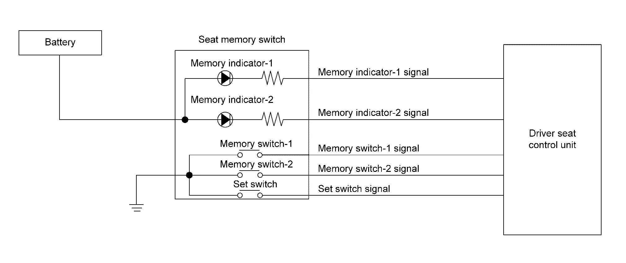
INDIVIDUAL COMPONENT FUNCTION
-
When the set switch is pressed, it transmits set switch signal to driver seat control unit.
-
When memory switch 1 or 2 is pressed, it transmits memory switch 1 or 2 signal to driver seat control unit.
-
Driver seat control unit illuminates memory switch 1 or 2 indicator when memory switch 1 or 2 is pressed.
Other materials:
P0441 Evap Control System
DTC Description
DTC DETECTION LOGICIn this evaporative emission (EVAP)
control system, purge flow occurs during non-closed throttle conditions.
Purge volume is related to air intake volume. Under normal purge
conditions (non-closed throttle), the EVAP canister purge volume control
solenoid ...
Comment utiliser le HUD (Affichage Tête Haute) de votre Nissan Rogue
Informations de base et activation
LŌĆÖutilisation du syst├©me dŌĆÖaffichage t├¬te haute (HUD) sur le Nissan Rogue est con├¦ue pour ├¬tre aussi simple qu'efficace. Pour activer cette technologie de projection laser, il vous suffit d'appuyer sur la commande d├®di├®e "HUD" situ├®e sur le pannea ...
P11b0 Vcr Target Angle (cold Start)
DTC Description
DTC DETECTION LOGIC DTC
CONSULT screen terms
(Trouble diagnosis content)
DTC detection condition
P11B0
00
VCR target angle (cold start)
[Variable compression ratio target angle (cold start)]
Diagnosis condition
Engine cold start
Signal (terminal)
Ō ...