Nissan Rogue Service Manual: System description
COMPONENT PARTS
BODY CONTROL SYSTEM
BODY CONTROL SYSTEM : Component Parts Location
- BCM
- Behind instrument panel (LH)
POWER CONSUMPTION CONTROL SYSTEM
POWER CONSUMPTION CONTROL SYSTEM : Component Parts Location
- Combination meter Refer to MWI-6, "METER SYSTEM : Component Parts Location".
- IPDM E/R Refer to PCS-4, "Component Parts Location".
- BCM Refer to BCS-7, "BODY CONTROL SYSTEM : Component Parts Location".
SYSTEM
BODY CONTROL SYSTEM
BODY CONTROL SYSTEM : System Description
OUTLINE
- BCM (body control module) controls various electrical components. It receives the information required from CAN communication and the signals received from each switch and sensor.
- BCM has a combination switch reading function for reading the
status of combination switches (light, turn
signal, wiper and washer) in addition to functions for controlling the
operation of various electrical components.
It also has a signal transmission function for other systems, and a power consumption control function that reduces the power consumption with the ignition switch OFF.
- • BCM is equipped with a diagnosis function that operates with CONSULT and allows for various settings to be changed.
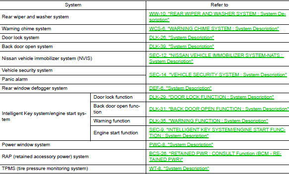
BCM FUNCTION LIST
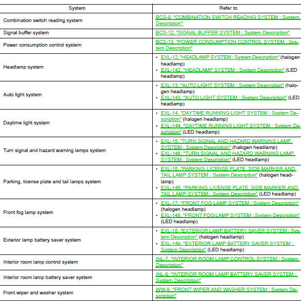
COMBINATION SWITCH READING SYSTEM
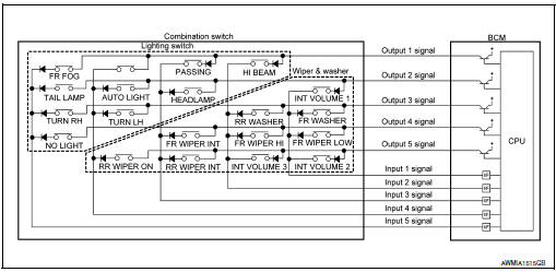
COMBINATION SWITCH READING SYSTEM : System Description
SYSTEM DIAGRAM
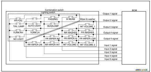
OUTLINE
- BCM reads the status of the combination switch (light, turn signal, wiper and washer) and recognizes the status of each switch.
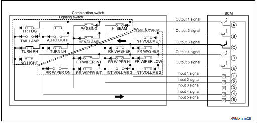
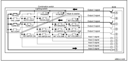
- BCM has a combination of 5 output terminals (OUTPUT 1 - 5) and 5 input terminals (INPUT 1 - 5) and reads a maximum of 20 switch states.
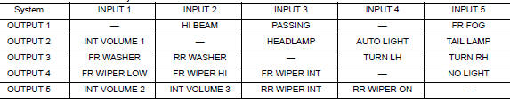
COMBINATION SWITCH MATRIX
Combination switch circuit
Combination switch INPUT-OUTPUT system list
COMBINATION SWITCH READING FUNCTION
Description
- BCM reads the status of the combination switch at 10 ms intervals normally.
NOTE: BCM reads the status of the combination switch at 60 ms intervals when BCM is controlled at low power consumption control mode.
- BCM operates as follows and judges the status of the combination switch.
- It operates the transistor on OUTPUT side in the following order: OUTPUT 1 → 2 → 3 → 4 → 5, and outputs voltage waveform.
- The voltage waveform of OUTPUT corresponding to the formed circuit is input into the interface on INPUT side if any (1 or more) switches are ON.
- It reads this change of the voltage as the status signal of the combination switch.
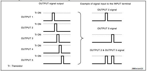
Operation Example
In the following operation example, the combination of the status signals of the combination switch is replaced as follows: INPUT 1 - 5 to “1 - 5” and OUTPUT 1 - 5 to “A - E”.
Example 1: When a switch (TURN RH) is turned ON
- The circuit between OUTPUT 3 and INPUT 5 is formed when the TURN RH switch is turned ON.
- BCM detects the combination switch status signal “5C” when the signal of OUTPUT 3 is input to INPUT 5.
- BCM judges that the TURN RH switch is ON when the signal “5C” is detected.
Example 2: When some switches (FR FOG, TURN RH) are turned ON
- The circuits between OUTPUT 1 and INPUT 5 and between OUTPUT 3 and INPUT 5 are formed when the FR FOG switch and TURN RH switch are turned ON.
- BCM detects the combination switch status signal “5AC” when the signals of OUTPUT 1 and OUTPUT 3 are input to INPUT 5.
- BCM judges that the FR FOG switch and TURN RH switch are ON when the signal “5AC” is detected.
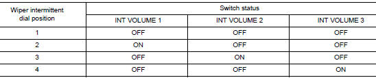
WIPER INTERMITTENT DIAL POSITION SETTING (FRONT WIPER INTERMITTENT OPERATION)
BCM judges the wiper intermittent dial 1 - 4 by the status of INT VOLUME 1, 2, and 3 switches.
SIGNAL BUFFER SYSTEM
SIGNAL BUFFER SYSTEM : System Description
SYSTEM DIAGRAM
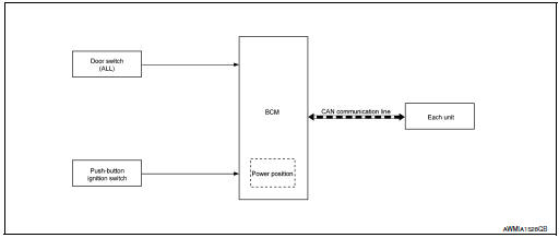
OUTLINE
BCM has the signal transmission function that outputs/transmits each input/received signal to each unit.
SIGNAL TRANSMISSION FUNCTION LIST
|
Signal name |
Input |
Output |
Description |
|
Engine switch (push switch) | IPDM E/R (CAN) | Inputs the push-button ignition switch (push switch) signal and transmits the ignition switch status judged with BCM via CAN communication. |
| Door switch signal | Any door switch |
|
Inputs the door switch signal and transmits it via CAN communication. |
POWER CONSUMPTION CONTROL SYSTEM
POWER CONSUMPTION CONTROL SYSTEM : System Description
SYSTEM DIAGRAM
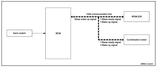
OUTLINE
- BCM incorporates a power saving control function that reduces the power consumption according to the vehicle status.
- BCM switches the status (control mode) by itself with the power saving control function. It performs the sleep request to each unit (IPDM E/R and combination meter) that operates with the ignition switch OFF.
Normal mode (wake-up)
- CAN communication is normally performed with other units
- Each control with BCM is operating properly
CAN communication sleep mode (CAN sleep)
- CAN transmission is stopped
- Control with BCM only is operating
Low power consumption mode (BCM sleep)
- Low power consumption control is active
- CAN transmission is stopped
LOW POWER CONSUMPTION CONTROL WITH BCM
BCM reduces the power consumption with the following operation in the low power consumption mode.
- The reading interval of each switch changes from 10 ms interval to 60 ms interval.
SLEEP MODE ACTIVATION
- BCM receives the sleep-ready signal (ready) from IPDM E/R and combination meter via CAN communication.
- BCM transmits the sleep wake up signal (sleep) to each unit when all of the CAN sleep conditions are fulfilled.
- Each unit stops the transmission of CAN communication with the sleep wake-up signal. BCM is in CAN communication sleep mode.
- BCM is in the low power consumption mode and performs the low power consumption control when all of the BCM sleep conditions are fulfilled with CAN sleep condition.
Sleep condition
|
CAN sleep condition |
BCM sleep condition |
|
|
WAKE-UP OPERATION
- BCM changes from the low power consumption mode to the CAN communication sleep mode when the any of the BCM wake-up conditions are fulfilled. Only the control with BCM is activated.
- BCM transmits the sleep wake-up signal (wake up) to each unit when any of the CAN wake-up conditions are fulfilled. It changes from the low power consumption mode or the CAN communication sleep mode to the normal mode.
- Each unit starts the transmission of CAN communication with the sleep wake-up signal. In addition, the combination meter transmits the wake-up signal to BCM via CAN communication to report the CAN communication start.
|
BCM wake-up condition |
CAN wake-up condition |
|
|
SHIPPING MODE CONTROL SYSTEM
SHIPPING MODE CONTROL SYSTEM : System Description
SYSTEM DIAGRAM
DESCRIPTION
- BCM switches the status (shipping mode or normal mode) by itself according to the extended storage fuse switch condition, and transmits shipping mode status signal to combination meter and each unit via CAN communication.
- When shipping mode function operates, each control unit does not detect DTCs.
- BCM control functions are limited in shipping mode. Refer to BCS-74, "Description".
- The combination meter displays extended storage fuse warning message* on the information display, and turns the turn signal indicator lamp (LH/RH) ON, when BCM is in shipping mode.
*: When shipping mode function operates, “SHIPPING MODE ON PUSH STORAGE FUSE” is displayed.
DIAGNOSIS SYSTEM (BCM)
COMMON ITEM
COMMON ITEM : CONSULT Function (BCM - COMMON ITEM)
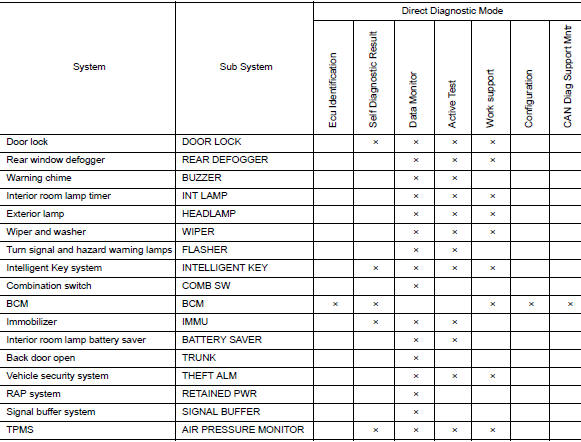
APPLICATION ITEM
CONSULT performs the following functions via CAN communication with BCM.
|
Direct Diagnostic Mode |
Description |
| Ecu Identification | The BCM part number is displayed. |
| Ecu Identification | The BCM self diagnostic results are displayed. |
| Data Monitor | The BCM input/output data is displayed in real time. |
| Active Test | The BCM activates outputs to test components. |
| Work support | The settings for BCM functions can be changed. |
| Configuration |
|
| CAN Diag Support Mntr | The result of transmit/receive diagnosis of CAN communication is displayed. |
SYSTEM APPLICATION
BCM can perform the following functions.
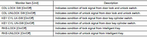
DOOR LOCK
DOOR LOCK : CONSULT Function (BCM - DOOR LOCK)
SELF DIAGNOSTIC RESULT
Refer to BCS-48, "DTC Index".
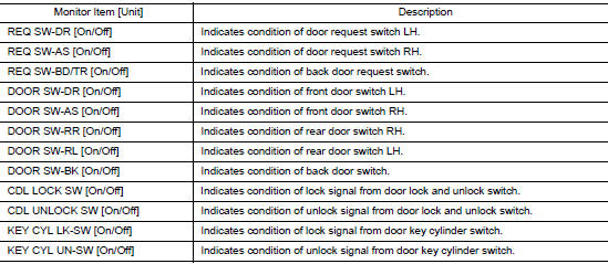
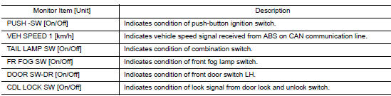
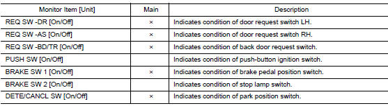
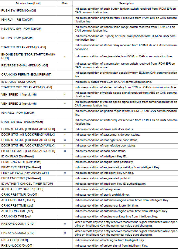
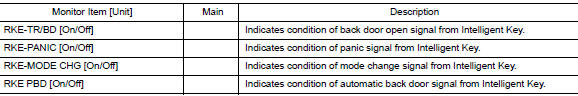
DATA MONITOR
ACTIVE TEST

WORK SUPPORT
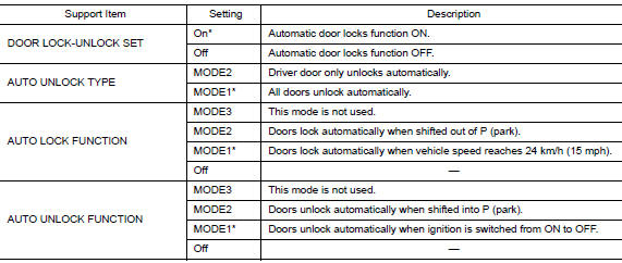
* : Initial setting
REAR DEFOGGER
REAR DEFOGGER : CONSULT Function (BCM - REAR DEFOGGER)
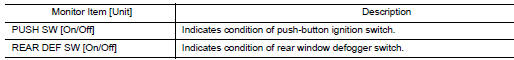
DATA MONITOR
ACTIVE TEST

WORK SUPPORT
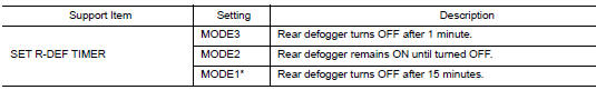
* : Initial setting
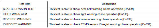
BUZZER
BUZZER : CONSULT Function (BCM - BUZZER)
DATA MONITOR
ACTIVE TEST
INT LAMP
INT LAMP : CONSULT Function (BCM - INT LAMP)
DATA MONITOR
ACTIVE TEST

WORK SUPPORT
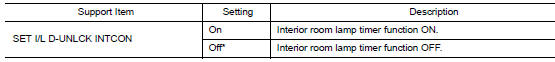
*: Initial setting
HEADLAMP
HEADLAMP : CONSULT Function (BCM - HEADLAMP)
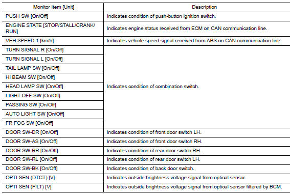
DATA MONITOR
WORK SUPPORT
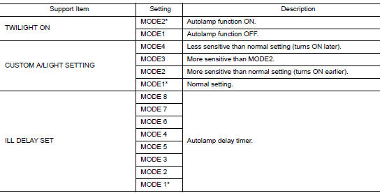
*: Initial setting
WIPER
WIPER : CONSULT Function (BCM - WIPER)
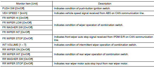
DATA MONITOR
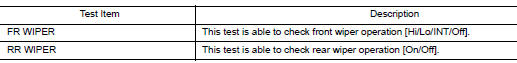
ACTIVE TEST
WORK SUPPORT
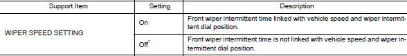
*: Initial Setting
FLASHER
FLASHER : CONSULT Function (BCM - FLASHER)
DATA MONITOR
ACTIVE TEST

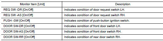
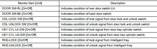
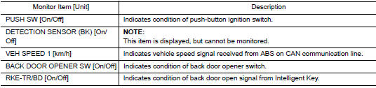
INTELLIGENT KEY
INTELLIGENT KEY : CONSULT Function (BCM - INTELLIGENT KEY)
SELF DIAGNOSTIC RESULT
Refer to BCS-48, "DTC Index".
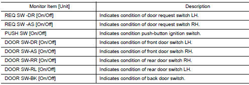
DATA MONITOR
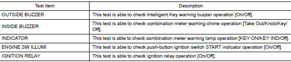
ACTIVE TEST
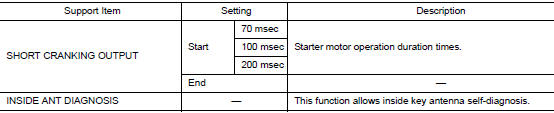
WORK SUPPORT
COMB SW
COMB SW : CONSULT Function (BCM - COMB SW)
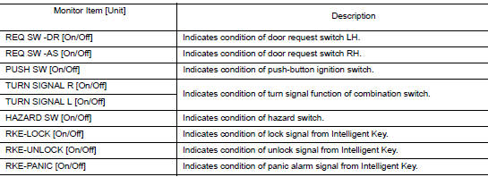
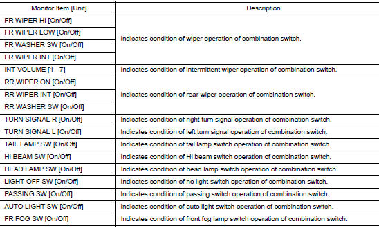
DATA MONITOR
BCM
BCM : CONSULT Function (BCM - BCM)
ECU IDENTIFICATION
The BCM part number is displayed.
SELF DIAGNOSTIC RESULT
Refer to BCS-48, "DTC Index".
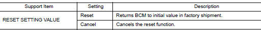
WORK SUPPORT
CONFIGURATION
Refer to BCS-61, "CONFIGURATION (BCM) : Description".
CAN DIAG SUPPORT MNTR
Refer to LAN-14, "CAN Diagnostic Support Monitor".
IMMU
IMMU : CONSULT Function (BCM - IMMU)
SELF DIAGNOSTIC RESULT
Refer to BCS-48, "DTC Index".
DATA MONITOR

ACTIVE TEST

WORK SUPPORT

BATTERY SAVER
BATTERY SAVER : CONSULT Function (BCM - BATTERY SAVER)
DATA MONITOR
ACTIVE TEST

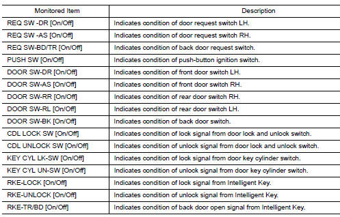
TRUNK
TRUNK : CONSULT Function (BCM - TRUNK)
DATA MONITOR
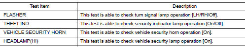
THEFT ALM
THEFT ALM : CONSULT Function (BCM - THEFT ALM)
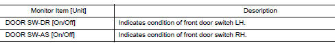
DATA MONITOR
ACTIVE TEST
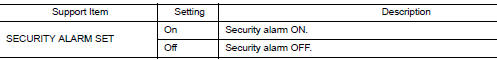
WORK SUPPORT
RETAINED PWR
RETAINED PWR : CONSULT Function (BCM - RETAINED PWR)
DATA MONITOR
SIGNAL BUFFER
SIGNAL BUFFER : CONSULT Function (BCM - SIGNAL BUFFER)
DATA MONITOR

AIR PRESSURE MONITOR
AIR PRESSURE MONITOR : CONSULT Function (BCM-AIR PRESSURE MONITOR)
NOTE: The Signal Tech II Tool (J-50190) can be used to perform the following functions. Refer to the Signal Tech II User Guide for additional information.
- Activate and display TPMS sensor IDs
- Display tire pressure reported by the TPMS sensor
- Read TPMS DTCs
- Register TPMS sensor IDs
- Check Intelligent Key relative signal strength
- Confirm vehicle Intelligent Key antenna signal strength
SELF DIAGNOSTIC RESULT
NOTE: Before performing Self Diagnostic Result, be sure to register the sensor ID or the actual malfunction may be different from that displayed on CONSULT.
Refer to BCS-48, "DTC Index".
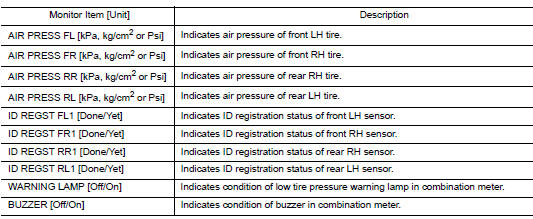
DATA MONITOR
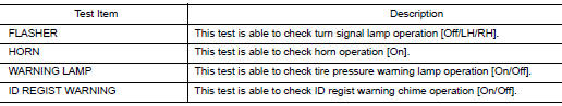
ACTIVE TEST
WORK SUPPORT
 Preparation
Special Service Tool
The actual shape of the tools may differ from those tools illustrated here.
Tool number
(TechMate No.)
Tool name
Description
—
(J-50190)
...
 ECU diagnosis information
BCM
Reference Value
NOTE:
The Signal Tech II Tool (J-50190) can be used to perform the following
functions. Refer to the Signal Tech II
User Guide for additional information.
Activate ...
Other materials:
Coil spring
Exploded View
Upper seat
Coil spring
Lower seat
Rubber washer (LH/RH)
Rear suspension arm
Front
Removal and Installation - FWD
REMOVAL
Remove the rear wheel and tire using power tool.
Remove the bolt and separate the rear wheel sensor from the wheel h ...
Low tire pressure warning lamp blinks
Description
The low tire pressure warning lamp blinks when the power switch is turned ON.
NOTE:
The position of an inactive tire pressure sensor can be identified by checking
the blinking timing of the low tire
pressure warning lamp.
Diagnosis Procedure
1.TIRE PRESSURE SENSOR ID REGISTRA ...
System description
COMPONENT PARTS
Component Parts Location
View right of steering column.
No.
Component
Function
1
Combination meter
Combination meter transmits the vehicle speed signal to BCM via CAN
communication.
BCM also receives the vehicle speed signal f ...
