Nissan Rogue Service Manual: System description
COMPONENT PARTS
Component Parts Location
|
No. |
Component |
Function |
| 1 | Combination meter | Combination meter transmits the vehicle speed signal to BCM via CAN
communication. BCM also receives the vehicle speed signal from ABS actuator and electric unit (control unit) via CAN communication. BCM compares both signals to detect the vehicle speed. Security indicator lamp is located on combination meter. Security indicator lamp blinks when ignition switch is in any position other than ON to warn that NISSAN VEHICLE IMMOBILIZER SYSTEM-NATS [NVIS (NATS)] is on board. Refer to MWI-6, "METER SYSTEM : Component Parts Location". |
| 2 | Ignition switch | Ignition switch transmits ON/OFF signal to BCM. BCM changes the ignition switch position with the operation of ignition switch. |
| 3 | NATS antenna amp. | Refer to SEC-116, "NATS Antenna Amp.". |
| 4 | Hood switch | Hood switch detects Hood open/close condition and then transmits ON/OFF signal to IPDM E/R. |
| 5 | Transmission range switch | Refer to TM-14, "CVT CONTROL SYSTEM : Transmission Range Switch". |
| 6 | IPDM E/R | Refer to PCS-4, "Component Parts Location". |
| 7 | Stop lamp switch | Refer to BRC-12, "Stop Lamp Switch". |
| 8 | BCM | BCM controls NISSAN VEHICLE IMMOBILIZER SYSTEM-NATS [NVIS
(NATS)] and VEHICLE SECURITY SYSTEM. Then, when the ignition switch is turned ON, BCM performs ID verification between BCM and ECM. If the ID verification result is OK, ECM can start engine. Refer to BCS-79, "BODY CONTROL SYSTEM : Component Parts Location" for detailed installation location. |
| 9 | CVT shift selector | Refer to TM-12, "CVT CONTROL SYSTEM : Component Parts Location". |
| 10 | Main power window and door lock/unlock switch | Door lock and unlock switch is integrated into the power window main
switch. Door lock and unlock switch transmits door lock/unlock operation signal to BCM. Refer to PWC-7, "Power Window Main Switch". |
| 11 | Front door lock assembly LH | Door key cylinder switch is integrated into front door lock assembly
(driver
side). Door key cylinder switch detects door LOCK/UNLOCK operation using mechanical key, and then transmits the operation signal to BCM. Refer to DLK-285, "Front Door Lock Assembly (Driver Side)". |
| 12 | Front door lock assembly LH | Door switch detects door open/close condition and then transmits ON/OFF signal to BCM. |
| 13 | Rear door switch LH | Door switch detects door open/close condition and then transmits ON/OFF signal to BCM. |
| 14 | Front door switch RH | Door switch detects door open/close condition and then transmits ON/OFF signal to BCM. |
| 15 | Back door lock assembly | Back door lock actuator locks/unlocks the back door latch assembly. |
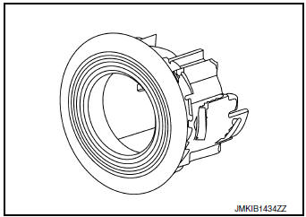
NATS Antenna Amp.
The ID verification is performed between BCM and transponder integrated into key via NATS antenna amp. when key backside is contacted to ignition switch in case that key battery is discharged. If the ID verification result is OK, the operation of ignition switch is available.
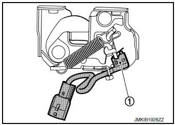
Hood Switch
Hood switch 1 detects that hood is open, and then transmits ON/ OFF signal to IPDM E/R. IPDM E/R transmits hood switch signal to BCM via CAN communication. Hood switch is integrated into hood lock assembly LH.
SYSTEM
NISSAN VEHICLE IMMOBILIZER SYSTEM-NATS
NISSAN VEHICLE IMMOBILIZER SYSTEM-NATS : System Diagram
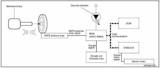
NISSAN VEHICLE IMMOBILIZER SYSTEM-NATS : System Desc
INPUT/OUTPUT SIGNAL CHART
BCM
|
Switch/Input signal |
Input signal to BCM |
BCM function |
Actuator/Output signal |
| NATS antenna amp. | Key ID | NATS |
|
| ECM | Engine status signal |
SYSTEM DESCRIPTION
NATS (Nissan Anti-Theft System) has the following immobilizer functions:
- Engine immobilizer shows high anti-theft performance to prevent engine from starting by anyone other than the owner.
- Only a key with key ID registered in BCM and ECM can start engine, and shows high anti-theft performance to prevent key from being copied or stolen.
- Security indicator always flashes with mechanical key removed condition (key switch: OFF) and ignition knob released condition on LOCK position (ignition knob switch: OFF).
- Therefore, NATS warns outsiders that the vehicle is equipped with the anti-theft system.
- If system detects malfunction, security indicator illuminates when ignition switch is turned to ON position.
- If the owner requires, ignition key ID or mechanical key ID can be registered for up to 4 keys.
- During trouble diagnosis or when the following parts have been replaced, and if ignition key is added, registration* 1 is required.
*1: All keys kept by the owner of the vehicle should be registered with mechanical key.
- ECM
- BCM
- Ignition key
- Remote keyless entry receiver
- NATS trouble diagnosis, system initialization and additional
registration of other mechanical key IDs must be
carried out using CONSULT.
When NATS initialization has been completed, the ID of the inserted mechanical key or mechanical key IDs can be carried out.
- Possible symptom of NATS malfunction is “Engine cannot start”. Identify the possible causes according to “Work Flow”, Refer to SEC-150, "Work Flow".
- If ECM other than Genuine NISSAN is installed, the engine cannot be started. For ECM replacement procedure, refer to SEC-153, "ECM RE-COMMUNICATING FUNCTION : Description".
PRECAUTIONS FOR KEY REGISTRATION
- The key registration is a procedure that erases the current NATS
ID once, and then re-registers a new ID.
Therefore the registered key is necessary for this procedure. Before starting the registration procedure, collect all registered Keys from the customer.
- The NATS ID registration is the procedure that registers the ID
stored into the transponder (integrated in
mechanical key) to BCM.
The key ID registration is the procedure that registers the ID to the BCM.
- When performing the key system registration only, the engine cannot be started by inserting the key into the key cylinder. When performing the NATS registration only, the engine cannot be started by using the ignition key.
SECURITY INDICATOR
- Always flashes with ignition key in the OFF position.
MAINTENANCE INFORMATION
CAUTION: It is necessary to perform NATS ID registration when replacing any of the following parts.
If ID registration is not performed, the electrical system may not operate properly.
- BCM
- ECM
- IPDM E/R
- Ignition key
- NATS antenna amp.
- Combination meter
VEHICLE SECURITY SYSTEM
VEHICLE SECURITY SYSTEM : System Diagram
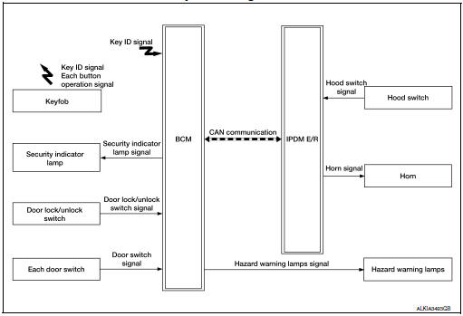
VEHICLE SECURITY SYSTEM : System Description
- The vehicle security system has two alarm functions (theft warning alarm and panic alarm), and reduces the possibility of a theft or mischief by activating horns (and hazard warning lamps) intermittently.
- The panic alarm does not start when the theft warning alarm is activating, and the panic alarm stops when the theft warning alarm is activated.
The priority of the functions are as per the following.

THEFT WARNING ALARM
- The theft warning alarm function activates horns and hazard warning lamps intermittently when BCM detects that any door or hood is opened by unauthorized means, while the system is in the ARMED state.
- Security indicator lamp on combination meter always blinks when ignition switch is in any position other than ON. Security indicator lamp blinking warns that the vehicle is equipped with a vehicle security system.
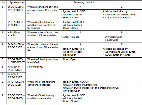
Operation Flow
NOTE:
- To lock/unlock all doors by operating remote controller button of keyfob, the keyfob must be within the detection area of BCM. For details, refer to DLK-288, "REMOTE KEYLESS ENTRY SYSTEM : System Description".
DISARMED Phase
The vehicle security system is not set in the DISARMED phase. The vehicle security system stays in this phase while any door is open, because it is assumed that the owner is inside or nearby the vehicle. Security indicator lamp blinks every 2.4 seconds.
When the vehicle security system is reset, each phase switches to the DISARMED phase directly.
PRE-ARMED Phase
The PRE-ARMED phase is the transient state between the DISARMED phase and the ARMED phase. This phase is maintained for 30 seconds, so that the owner can reset the setting due to a mis-operation. This phase switches to the ARMED phase when vehicle conditions are not changed for 30 seconds. Security indicator lamp illuminates while being in this phase.
To reset the PRE-ARMED phase, refer to the switching condition of No. 10 in the table above.
ARMED Phase
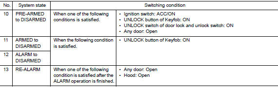
The vehicle security system is set, and BCM monitors all necessary inputs. If any door or hood is opened without using Keyfob, vehicle security system switches to the ALARM phase. Security indicator lamp blinks every 2.4 seconds.
To reset the ARMED phase, refer to the switching condition of No. 11 in the table above.
ALARM Phase
BCM transmits “Theft Warning Horn Request” signal intermittently to IPDM E/R via CAN communication, and blinks hazard warning lamps. In this phase, horns and hazard warning lamps are activated intermittently for approximately 27.5 seconds to warn that the vehicle is accessed by unauthorized means. After 27.5 seconds, the vehicle security system returns to the ARMED phase. At this time, if BCM still detects unauthorized access to the vehicle, the system is switched to the ALARM phase again. This RE-ALARM operation is carried out a maximum of 3 times.
To cancel the ALARM operation, refer to the switching condition of No. 12 in the table above.
NOTE: If a battery terminal is disconnected during the ALARM phase, theft warning alarm stops. But when the battery terminal is reconnected, theft warning alarm is activated again.
PRE-RESET Phase
The PRE-RESET phase is the transient state between each phase and DISARMED phase. If only the condition of hood is not satisfied, the system switches to the PRE-RESET phase. Then, when any condition is changed, the system switches to the DISARMED phase or PRE-ARMED phase.
PANIC ALARM
The panic alarm function activates horns intermittently when the owner presses PANIC ALARM button of Keyfob outside the vehicle while ignition switch is OFF.
For details, refer to SEC-118, "VEHICLE SECURITY SYSTEM : System Description".
DIAGNOSIS SYSTEM (BCM)
COMMON ITEM
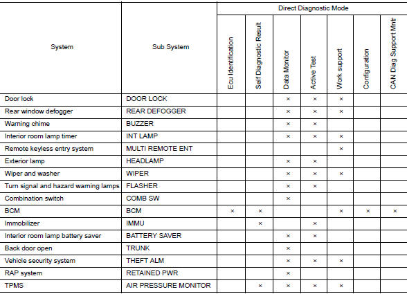
COMMON ITEM : CONSULT Function (BCM - COMMON ITEM)
APPLICATION ITEM
CONSULT performs the following functions via CAN communication with BCM.
|
Direct Diagnostic Mode |
Description |
| Ecu Identification | The BCM part number is displayed. |
| Self Diagnostic Result | The BCM self diagnostic results are displayed. |
| Data Monitor | The BCM input/output data is displayed in real time. |
| Active Test | The BCM activates outputs to test components. |
| Work support | The settings for BCM functions can be changed. |
| Configuration |
|
| CAN Diag Support Mntr | The result of transmit/receive diagnosis of CAN communication is displayed. |
SYSTEM APPLICATION
BCM can perform the following functions.
IMMU
IMMU : CONSULT Function (BCM - IMMU)
SELF DIAGNOSTIC RESULT
Refer to BCS-108, "DTC Index".
ACTIVE TEST

WORK SUPPORT

THEFT ALM
THEFT ALM : CONSULT Function (BCM - THEFT ALM)
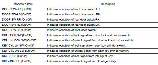
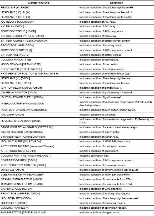
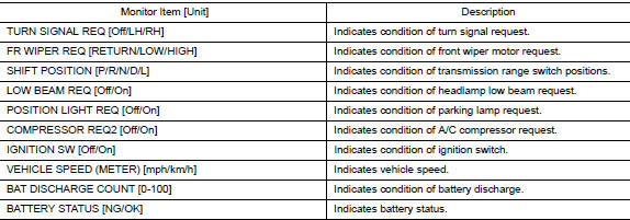
DATA MONITOR
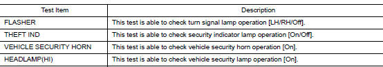
ACTIVE TEST
WORK SUPPORT

DIAGNOSIS SYSTEM (IPDM E/R)
CONSULT Function (IPDM E/R)
APPLICATION ITEM
CONSULT performs the following functions via CAN communication with IPDM E/R.
|
Direct Diagnostic Mode |
Description |
| Ecu Identification | The IPDM E/R part number is displayed. |
| Self Diagnostic Result | The IPDM E/R self diagnostic results are displayed. |
| Data Monitor | The IPDM E/R input/output data is displayed in real time. |
| Active Test | The IPDM E/R activates outputs to test components. |
| CAN Diag Support Mntr | The result of transmit/receive diagnosis of CAN communication is displayed. |
ECU IDENTIFICATION
The IPDM E/R part number is displayed.
SELF DIAGNOSTIC RESULT
Refer to PCS-20, "DTC Index".
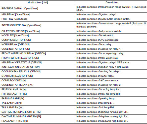
DATA MONITOR
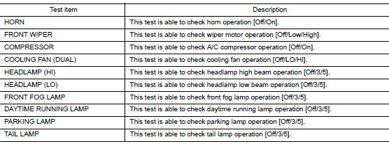
ACTIVE TEST
CAN DIAG SUPPORT MNTR
Refer to LAN-14, "CAN Diagnostic Support Monitor".
 Precaution
Precaution for Supplemental Restraint System (SRS) "AIR BAG" and "SEAT
BELT
PRE-TENSIONER"
The Supplemental Restraint System such as “AIR BAG” and “SEAT BELT PRE-TENSIONE ...
 ECU diagnosis information
ECM, IPDM E/R, BCM
List of ECU Reference
...
Other materials:
Ambient sensor signal circuit
Description
It detects outside air temperature and converts it into a resistance value
which is then input into the combination
meter.
Diagnosis Procedure
Regarding Wiring Diagram information, refer to MWI-32, "Wiring Diagram".
1.CHECK AMBIENT SENSOR SIGNAL CIRCUIT
Turn ig ...
Key interlock cable
Exploded View
Key cylinder
Clip
Key interlock cable
Shift selector assembly
Removal and Installation
REMOVAL
CAUTION:
Always apply the parking brake before performing removal and installation.
Move shift selector to the “N” position.
Remo ...
Preparation
Special Service Tool
The actual shape of the tools may differ from those illustrated here.
Tool number
(TechMate No.)
Tool name
Description
—
(J-41425-NIS)
Aluminum tube repair kit
Repairing leaks in A/C tube
—
(J-38873-A)
Drive ...
