Nissan Rogue Service Manual: Key interlock cable
Exploded View
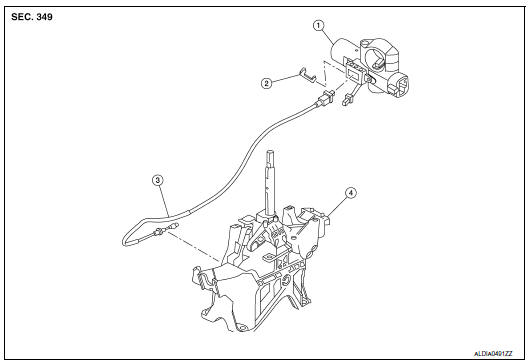
- Key cylinder
- Clip
- Key interlock cable
- Shift selector assembly
Removal and Installation
REMOVAL
CAUTION: Always apply the parking brake before performing removal and installation.
- Move shift selector to the “N” position.
- Remove the shift selector knob.
- Move shift selector to the “P” position.
- Remove the center console assembly. Refer to IP-18, "Removal and Installation".
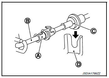
- Press the pawls (B) of the key interlock cable slider (A) while sliding it in the direction of the casing cap (C), and separate the adjusting holder (D) and slider.
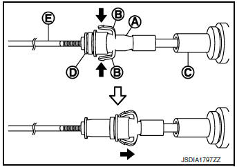
(E) :Key interlock rod
- Remove the key interlock cable from the shift selector.
- Remove the steering column covers. Refer to IP-17, "Removal and Installation".
- Remove instrument lower panel LH. Refer to IP-22, "Removal and Installation".
- Lift clip (A) in the direction of the arrow (
 C) and remove in the
direction of the arrow (
C) and remove in the
direction of the arrow (  D).
D).
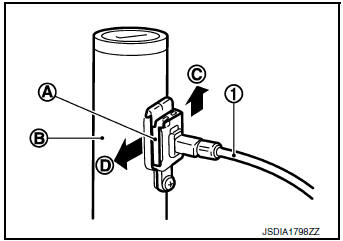
(1) :Key interlock cable
(B) :Key cylinder
- Disconnect the key interlock cable from the key cylinder.
- Disengage the clip and disconnect the key interlock cable from the vehicle.
INSTALLATION
Installation is in the reverse order of removal.
- While pressing the detent rod (B) down ( ), slide the key interlock cable slider (A) toward the key interlock rod (D) side, and install the adjusting holder (C) and key interlock rod.
CAUTION:
- Do not squeeze the pawls on the key interlock cable slider when holding the slider.
- Do not apply force in a perpendicular direction to the key interlock rod when sliding the slider.
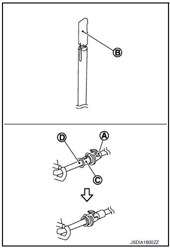
- Install the adjusting holder (A) onto the key interlock rod (B), then install the casing cap (C) onto the shift selector cable bracket (D).
CAUTION:
- When installing the key interlock cable, do not bend or twist the cable forcefully.
- After connecting the key interlock cable to the shift selector cable bracket, be sure to check that the casing cap is completely fastened to the cable bracket. If the casing cap is easily displaced, replace the key interlock cable.
Inspection
INSPECTION AFTER INSTALLATION
- Check the CVT position. If a malfunction is found, adjust the CVT position. Refer to TM-92, "Inspection".
- The key can be removed only when the selector lever is in the “P” position.
- It must not be possible to turn the ignition switch to LOCK when the selector lever is not in the “P” position
 Control cable
Exploded View
Shift selector
Control cable
Retainer grommet
Lock plate
Bracket
Manual lever
Transaxle assembly
Front
Removal and Installation
CAUTION:
Always apply ...
 TCM
TCM
Exploded View
Bracket
Bracket
TCM
: Vehicle front
: N·m (kg-m, in-lb)
Removal and Installation
CAUTION:
Do not impact the TCM when removing or installing TCM.
Wh ...
Other materials:
Parking brake rear cable
Removal and Installation
REMOVAL
Remove the center console assembly. Refer to IP-18, "Removal and
Installation".
Remove shift selector. Refer to TM-194, "Removal and
Installation".
Remove the bolts from the parking brake front cable mount. Refer
...
Preparation
Special Service Tool
The actual shape of the tool may differ from those illustrated here.
Tool number
(TechMate No.)
Tool name
Description
KV991J0080
(J-45741)
ABS active wheel sensor tester
Checking operation of ABS active wheel sensors
Comm ...
Basic inspection
DIAGNOSIS AND REPAIR WORKFLOW
Work Flow
DETAILED FLOW
1.COLLECT THE INFORMATION FROM THE CUSTOMER
Get the detailed information from the customer about the symptom (the
condition and the environment when
the incident/malfunction occurred) using the diagnosis worksheet.
>> GO TO 2.
2. ...
