Nissan Rogue Service Manual: TCM
Exploded View
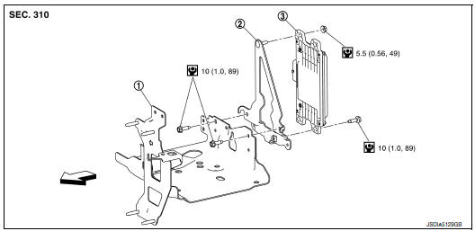
- Bracket
- Bracket
- TCM
 : Vehicle front
 : N┬Ęm (kg-m, in-lb)
Removal and Installation
CAUTION:
- Do not impact the TCM when removing or installing TCM.
- When replacing TCM and transaxle assembly as a set, replace transaxle assembly first and then replace TCM. Refer to TM-82, "Description".
- Before replacing TCM, save TCM data using "ADDITIONAL SERVICE
WHEN REPLACING TCM".
Refer to TM-82, "Work Procedure".
- When replacing TCM, note the ŌĆ£CVTF DETERIORATION DATEŌĆØ value displayed on CONSULT ŌĆ£CONFORM CVTF DETERIORTNŌĆØ in MAINTENANCE BOOKLET, before start the operation.
REMOVAL
- Disconnect the battery negative terminal. Refer to PG-75, "Exploded View".
- Remove the air duct (inlet). Refer to EM-24, "Exploded View".
- Disconnect the TCM harness connector (A).
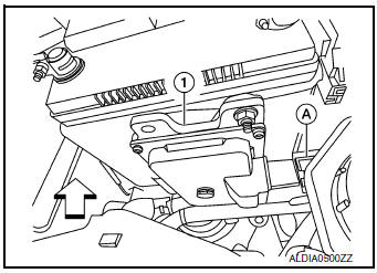
(1) : TCM
: Front
- Remove the TCM nuts and remove TCM from bracket.
INSTALLATION
Installation is in the reverse order of removal.
Adjustment
ADJUSTMENT AFTER INSTALLATION
Perform "ADDITIONAL SERVICE WHEN REPLACING TCM". Refer to TM-82, "Description".
 Key interlock cable
Exploded View
Key cylinder
Clip
Key interlock cable
Shift selector assembly
Removal and Installation
REMOVAL
CAUTION:
Always apply the parking brake before perf ...
 Air breather
Exploded View
Air breather
Air breather hose
Air breather tube
Transaxle assembly
: Vehicle front
Removal and Installation
REMOVAL
Remove air cleaner and air duct. Refer ...
Other materials:
How to follow trouble diagnoses
Description
NOTICE:
Trouble diagnoses indicate work procedures required to diagnose problems
effectively. Observe the following
instructions before diagnosing.
Before performing trouble diagnoses, read the ŌĆ£Work FlowŌĆØ in each
section.
After repairs, re-check that the pr ...
ECU diagnosis information
DIAGNOSIS SENSOR UNIT
DTC Index
DIAGNOSTIC CODE CHART
NOTE:
Follow the procedures in numerical order when repairing malfunctioning parts.
Confirm whether malfunction is
eliminated using air bag warning lamp or CONSULT each time repair is finished.
If malfunction is still
observed, proceed ...
Excessive operation frequency
Description
VDC function, TCS function, ABS function, EBD function, Brake limited slip
differential (BLSD) function, Brake
assist function, hill start assist function or Brake force distribution function
operates in excessive operation frequency.
Diagnosis Procedure
1.CHECK BRAKING FORCE
Ch ...
