Nissan Rogue Service Manual: Control cable
Exploded View
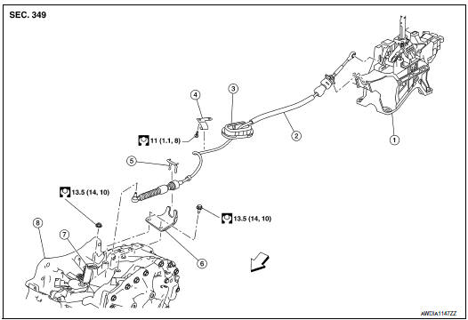
- Shift selector
- Control cable
- Retainer grommet
- Lock plate
- Bracket
- Manual lever
- Transaxle assembly
 Front
Front
Removal and Installation
CAUTION: Always apply the parking brake before performing removal and installation.
REMOVAL
- Apply the parking brake.
CAUTION: Make sure the vehicle cannot move with the parking brake applied.
- Remove battery tray. Refer to PG-76, "Removal and Installation (Battery Tray)".
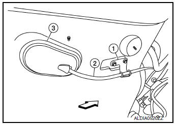
- Remove the control cable nut (
 ) and remove the control cable
(1) from the manual lever (2).
) and remove the control cable
(1) from the manual lever (2).
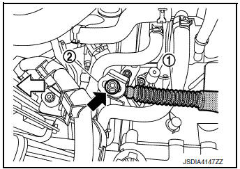
 : Front
- Remove the lock plate (1) and remove the control cable (2) from bracket (3).
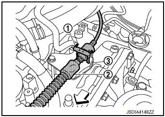
: Front
- Remove the center console assembly. Refer to IP-18, "Removal and Installation".
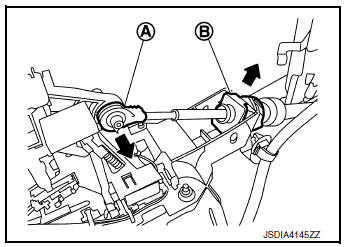
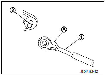
- Disconnect the tip (A) of control cable and remove the socket (B) from the CVT shift selector assembly.
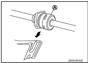
- Remove the control cable (1) from bracket (2).
- Remove by pushing retainer grommet (3) upward.
: Front
- Remove the control cable.
INSTALLATION
Installation is in the reverse order of removal.
- Pay attention to the following when connecting the control cable to the CVT shift selector assembly.
- When connecting the control cable (1) to the CVT shift selector
assembly (2), face the grooved surface of the rib (A) up and
insert the control cable until it stops.
NOTE: Apply multi-purpose grease to control cable eye before installation.
- Install the socket (A) onto the CVT shift selector assembly.
CAUTION:
- Place the socket onto the CVT shift selector assembly, then fasten it in place from above.
- Check that the pulling on the socket does not disconnect it.
Inspection and Adjustment
ADJUSTMENT AFTER INSTALLATION
Adjust the CVT position. Refer to TM-92, "Adjustment".
INSPECTION AFTER ADJUSTMENT
Check the CVT shift selector position after the adjustment. Refer to TM-92, "Inspection".
 CVT shift selector
Exploded View
Shift selector knob
Lock pin
Shift selector assembly
Control cable
Shift selector knob cover
Front
Removal and installation
REMOVAL
Apply the parking b ...
 Key interlock cable
Exploded View
Key cylinder
Clip
Key interlock cable
Shift selector assembly
Removal and Installation
REMOVAL
CAUTION:
Always apply the parking brake before perf ...
Other materials:
Symptom diagnosis
AUDIO SYSTEM
Symptom Table
RELATED TO AUDIO
Symptoms
Check items
Probable malfunction location
The disk cannot be removed
Audio unit
Malfunction in audio unit.
Refer to AV-18, "On Board Diagnosis Function".
No sound comes out or the le ...
Periodic maintenance
REAR WHEEL HUB AND HOUSING
Inspection
INSPECTION
Make sure the conditions (looseness, back lash) of each component and
component conditions (wear, damage)
are normal.
WHEEL HUB AND BEARING INSPECTION
Move wheel hub and bearing in the axial direction by hand. Make
sure there is no ...
Front regulator
Exploded View
Front door panel
Front door regulator
Front door power window motor
Front door glass run rear
Front door glass run front
Front door glass
Front door glass rubber run
Removal and Installation
REMOVAL
Remove the front door finisher. Refer to INT-15, ...
