Nissan Rogue Service Manual: System
WARNING CHIME SYSTEM
WARNING CHIME SYSTEM : System Description
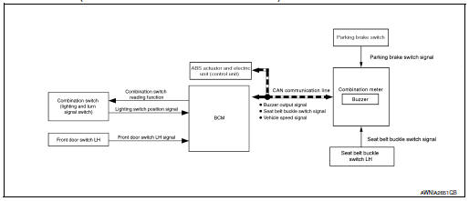
SYSTEM DIAGRAM (WITH INTELLIGENT KEY SYSTEM)
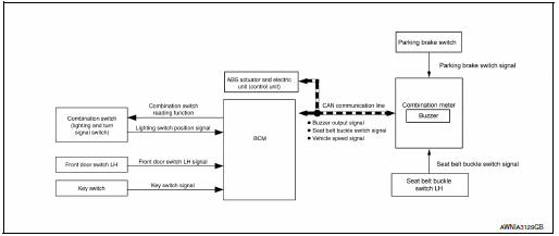
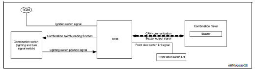
SYSTEM DIAGRAM (WITHOUT INTELLIGENT KEY SYSTEM)
COMBINATION METER INPUT/OUTPUT SIGNAL (CAN COMMUNICATION SIGNAL)
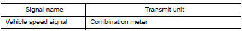
Input signal
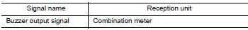
Output signal

BCM INPUT/OUTPUT SIGNAL (CAN COMMUNICATION SIGNAL)
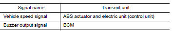
Input signal
Output signal
DESCRIPTION
Combination Meter
The combination meter sounds the alarm buzzer installed in the combination meter when receiving the buzzer output signal transmitted from each unit.
BCM
BCM receives signals from various units and transmits a buzzer output signal to the combination meter via CAN communication if it judges that the warning buzzer should be activated.
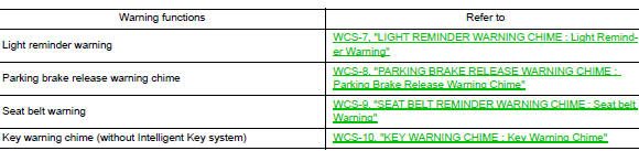
WARNING CHIME FUNCTION LIST
WARNING CHIME SYSTEM : Fail-safe
The combination meter activates the fail-safe control if CAN communication with each unit is malfunctioning.

LIGHT REMINDER WARNING CHIME
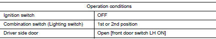
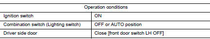
LIGHT REMINDER WARNING CHIME : Light Reminder Warning
WARNING CHIME OPERATION CONDITIONS
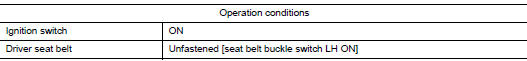
If all of the following conditions are fulfilled.
WARNING CHIME CANCEL CONDITIONS
Warning is canceled if any of the following conditions is fulfilled.
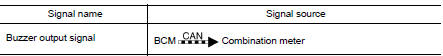
SIGNAL PATH
- BCM requires warning chime output to combination meter when it judges light reminder warning chime is necessary from signals below.
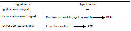
- Combination meter sounds integrated buzzer, following the warning chime output requirement (below signal) from BCM.
PARKING BRAKE RELEASE WARNING CHIME
PARKING BRAKE RELEASE WARNING CHIME : Parking Brake Release Warning Chime
SYSTEM DIAGRAM
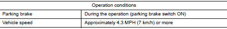
WARNING OPERATION CONDITIONS
If all of the following conditions are fulfilled

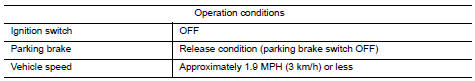
WARNING CANCEL CONDITIONS
Warning is canceled if any of the following conditions are fulfilled.
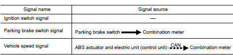
SIGNAL PATH
Combination meter sounds integrated buzzer when it judges that parking brake release warning chime is necessary from signals below.
SEAT BELT REMINDER WARNING CHIME
SEAT BELT REMINDER WARNING CHIME : Seat belt Warning
SYSTEM DIAGRAM
WARNING OPERATION CONDITIONS
If all of the following conditions are fulfilled.
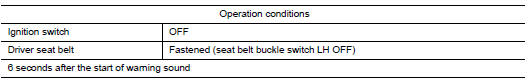
WARNING CANCEL CONDITIONS
Warning is canceled if any of the following conditions is fulfilled.
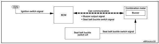
SIGNAL PATH
- BCM requires warning chime output to combination meter when it judges seat belt warning chime is necessary from signals below.
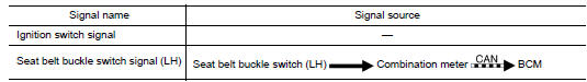
- Combination meter sounds integrated buzzer, following the warning chime output requirement (below signal) from BCM.

KEY WARNING CHIME
KEY WARNING CHIME : Key Warning Chime
SYSTEM DIAGRAM
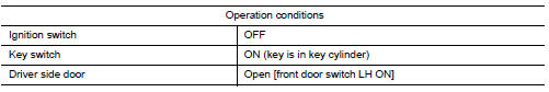
WARNING CHIME OPERATION CONDITIONS
If all of the following conditions are fulfilled.
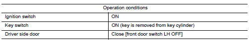
WARNING CHIME CANCEL CONDITIONS
Warning is canceled if any of the following conditions is fulfilled.
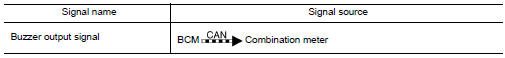
SIGNAL PATH
- BCM detects key inserted into the ignition switch, and sends key warning signal to combination meter with CAN communication line.

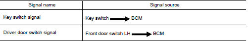
- Combination meter sounds integrated buzzer, when it receives a buzzer output signal from BCM.
 Component parts
Component Parts Location
No.
Component
Function
1
Key switch
Transmits the key switch signal to the BCM.
Refer to SEC-115, "Component Parts Locat ...
 Diagnosis system (combination meter)
Description
COMBINATION METER SELF-DIAGNOSIS MODE
The following meter functions can be checked during Combination Meter
Self-Diagnosis Mode:
Pointer sweep of speedometer, tachometer and ...
Other materials:
P0171 fuel injection system function
DTC Description
DTC DETECTION LOGIC
With the Air/Fuel Mixture Ratio Self-Learning Control, the actual mixture
ratio can be brought closely to the
theoretical mixture ratio based on the mixture ratio feedback signal from the
A/F sensors 1. The ECM calculates
the necessary compensation to corr ...
Corrosion protection
Most common factors contributing to vehicle
corrosion
Most vehicle corrosion is caused by:
the accumulation of moisture-retaining dirt
and debris in body panel sections, cavities,
and other areas
damage to paint and other protective coatings
caused by gravel and stone chip ...
Normal operating condition
Description
FRONT WIPER PROTECTION FUNCTION
IPDM E/R detects front wiper stop position by a front wiper stop position
signal.
When a front wiper stop position signal is in the conditions listed below, IPDM
E/R stops power supply to wiper
after repeating a front wiper 10 seconds activation ...
