Nissan Rogue Service Manual: Component parts
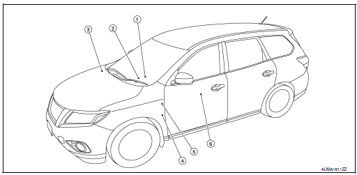
Component Parts Location
|
No. |
Component |
Function |
| 1 | Key switch | Transmits the key switch signal to the BCM.
Refer to SEC-115, "Component Parts Location" (without Intelligent Key system) for detailed installation location. |
| 2 | Combination meter |
|
| 3 | ABS actuator and electric unit (control unit) | Transmits the vehicle speed signal to the combination meter via CAN
communication.
Refer to BRC-8, "Component Parts Location" for detailed installation location. |
| 4 | Parking brake switch | Transmits the parking brake switch signal to the combination meter. |
| 5 | BCM | Based on the signals received from various units and switches,
transmits the buzzer output signal
to the combination meter via CAN communication.
Refer to BCS-7, "BODY CONTROL SYSTEM : Component Parts Location" (with Intelligent Key system) or BCS-79, "BODY CONTROL SYSTEM : Component Parts Location" (without Intelligent Key system) for detailed installation location. |
| 6 | Seat belt buckle switch LH | Transmits a seat belt buckle switch signal LH to the combination meter. |
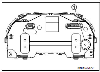
Combination Meter
The combination meter has a built-in buzzer (1) and sounds the following warnings, according to signals from each switch and unit:
- Light reminder warning
- Parking brake release warning chime
- Seat belt warning
- Key warning chime

 System
WARNING CHIME SYSTEM
WARNING CHIME SYSTEM : System Description
SYSTEM DIAGRAM (WITH INTELLIGENT KEY SYSTEM)
SYSTEM DIAGRAM (WITHOUT INTELLIGENT KEY SYSTEM)
COMBINATION METER INPUT/OUTPUT S ...
Other materials:
ABC warning lamp
Component Function Check
1.CHECK ABS WARNING LAMP FUNCTION
Check that ABS warning lamp in combination meter turns ON for 1 second after
ignition switch is turned ON.
CAUTION:
Never start the engine.
Is the inspection result normal?
YES >> Inspection End.
NO >> Proceed to BRC-1 ...
Active engine brake
The Active Engine Brake function adds subtle
deceleration by controlling CVT gear ratio, depending
on the cornering condition calculated
from driver’s steering input and plural sensors.
This benefit is for easier traceability and less
workload of adjusting speed with braking at corners.
...
USB (Universal Serial Bus) Connection Port (models without Navigation
System)
(if so equipped)
USB (Universal Serial Bus) Connection Port (models without Navigation System)
Connecting a device to the USB
Connection Port
WARNINGDo not connect, disconnect, or operate the
USB device while driving. Doing so can be
a distraction. If distracted you could lose
control of your ...
