Nissan Rogue Owners Manual: Active engine brake
The Active Engine Brake function adds subtle deceleration by controlling CVT gear ratio, depending on the cornering condition calculated from driverÔÇÖs steering input and plural sensors.
This benefit is for easier traceability and less workload of adjusting speed with braking at corners.
The Active Engine Brake also enhances braking feel by adding subtle deceleration with CVT gear ratio control according to driverÔÇÖs brake pedal operation The Active Engine Brake can be set to ON (enabled) or OFF (disabled) through the Vehicle Information Display ÔÇťSettingsÔÇŁ page. For additional information, refer to ÔÇťVehicle Information DisplayÔÇŁ in the ÔÇťInstruments and ControlsÔÇŁ section of this manual.
Active engine brake
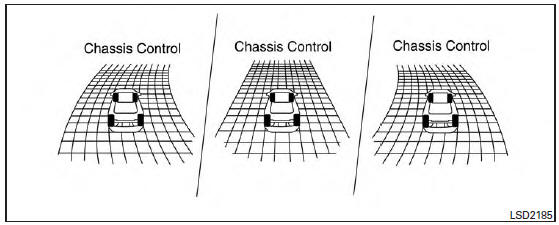
When the Active Engine Brake is operated at corners and the ÔÇťChassis ControlÔÇŁ mode is selected in the trip computer, the Active Engine Brake graphics are shown in the vehicle information display. For additional information, refer to ÔÇťTrip ComputerÔÇŁ in the ÔÇťInstruments and ControlsÔÇŁ section of this manual.
If the chassis control warning message appears in the vehicle information display, it may indicate that the Active Engine Brake is not functioning properly. Have the system checked by a NISSAN dealer as soon as possible.
| WARNING The Active Engine Brake may not be effective depending on the driving condition. Always drive carefully and attentively. |
When the Active Engine Brake is operating, the needle of the tachometer will rise up and you may hear an engine noise. This is normal and indicates that the active engine brake is operating properly.
 Active trace control
This system senses driving based on the driverÔÇÖs
steering and acceleration/braking patterns, and
controls brake pressure at individual wheels to
aid tracing at corners and help smooth vehicle
re ...
 Active ride control
This system senses upper body motion (based
on wheel speed information) and controls engine
torque and four wheel brake pressure. This will
enhance ride comfort in effort to restrain uncomfortable
...
Other materials:
Readiness for inspection/maintenance (I/M) test
WARNINGA vehicle equipped with All -Wheel Drive
(AWD) should never be tested using a two
wheel dynamometer (such as the dynamometers
used by some states for emissions
testing), or similar equipment. Make
sure you inform the test facility personnel
that your vehicle is equipp ...
Precaution
Precaution for Supplemental Restraint System (SRS) "AIR BAG" and "SEAT
BELT
PRE-TENSIONER"
The Supplemental Restraint System such as ÔÇťAIR BAGÔÇŁ and ÔÇťSEAT BELT PRE-TENSIONERÔÇŁ,
used along
with a front seat belt, helps to reduce the risk or severity of injury to the
...
Unbalance steering wheel turning force (torque variation)
Description
Unbalance steering wheel turning force (torque variation).
Diagnosis Procedure
1.PERFORM SELF-DIAGNOSIS
With CONSULT
Turn the ignition switch OFF to ON.
Perform ÔÇťEPSÔÇŁ self-diagnosis.
Is any DTC detected?
YES >> Check the DTC. Refer to STC-13, "DTC ...
