Nissan Rogue Owners Manual: Active trace control
This system senses driving based on the driver’s steering and acceleration/braking patterns, and controls brake pressure at individual wheels to aid tracing at corners and help smooth vehicle response.
The Active Trace Control can be set to ON (enabled) or OFF (disabled) through the Vehicle Information Display “Settings” page. For additional information, refer to “Vehicle Information Display” in the “Instruments and Controls” section of this manual.
When the VDC OFF switch is used to turn off the VDC system, the Active Trace Control is also turned off.
Active trace control
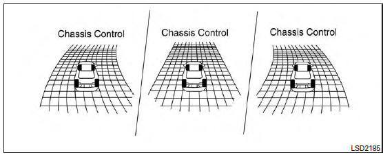
When the Active Trace Control is operated and the “Chassis Control”mode is selected in the trip computer, the Active Trace Control graphics are shown in the vehicle information display. For additional information, refer to “Trip Computer” in the “Instruments and Controls” section of this manual.
If the chassis control warning message appears in the vehicle information display, it may indicate that the Active Trace Control is not functioning properly. Have the system checked by a NISSAN dealer as soon as possible
| WARNING The active trace control may not be effective depending on the driving condition. Always drive carefully and attentively. |
When the Active Trace Control is operating, you may feel a pulsation in the brake pedal and hear a noise. This is normal and indicates that the active trace control is operating properly.
Even if the Active Trace Control is set to OFF, some functions will remain on to assist the driver (for example: avoidance scenes).
 Chassis Control
The chassis control is an electric control module
that includes the following functions:
Active Trace Control
Active Engine Brake
Active Ride Control
...
 Active engine brake
The Active Engine Brake function adds subtle
deceleration by controlling CVT gear ratio, depending
on the cornering condition calculated
from driver’s steering input and plural sensors.
This b ...
Other materials:
Trouble diagnosis - specification value
Description
The specification (SP) value indicates the tolerance of the value that is
displayed in “SPEC” of “DATA MONITOR”
mode of CONSULT during normal operation of the Engine Control System. When the
value in “SPEC” of
“DATA MONITOR” mode is within the SP value, the Engine ...
Sample/Wiring Diagram -Example-
Each section includes wiring diagrams.
Description
Number
Item
Description
1
Power supply
This means the power supply of fusible link or fuse.
2
Fuse
“/” means the fuse.
3
Current rating of fusible
...
Basic inspection
DIAGNOSIS AND REPAIR WORKFLOW
Work Flow
OVERALL SEQUENCE
DETAILED FLOW
1.GET INFORMATION FOR SYMPTOM
Get detailed information from the customer about the symptom (the
condition and the environment when
the incident/malfunction occurs).
Check operation condition of the ...
