Nissan Rogue Service Manual: Diagnosis system (combination meter)
Description
COMBINATION METER SELF-DIAGNOSIS MODE
The following meter functions can be checked during Combination Meter Self-Diagnosis Mode:
- Pointer sweep of speedometer, tachometer and gauges.
- Illumination of all LCD segments and color patterns for meter displays.
- Illumination of all lamps/LEDs that are controlled by the combination meter (regardless of switch status).
STARTING COMBINATION METER SELF-DIAGNOSIS MODE
NOTE:
- Check combination meter power supply and ground circuits if self-diagnosis mode does not start. Refer to MWI-59, "COMBINATION METER : Diagnosis Procedure". Replace combination meter if power supply and ground circuits are found to be normal and self-diagnosis mode does not start. Refer to MWI-82, "Removal and Installation".
- Combination meter self-diagnosis mode will function with the ignition switch in ON. Combination meter selfdiagnosis mode will exit upon turning the ignition switch to OFF.
How to Initiate Self-Diagnosis Mode
- Turn ignition switch OFF.
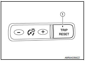
- While pressing the trip reset switch (1), turn ignition switch ON.
- Keep the trip reset switch for 1 seconds or more.
- Press the trip reset switch at least 3 times. (Within 7 seconds after the ignition switch is turned ON.)
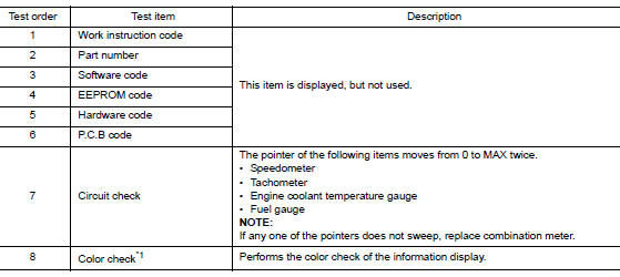
- ŌĆ£Work instruction codeŌĆØ is indicated in the top portion of information display and self-diagnosis is started.
- The mode switches in the order shown below each time the trip
reset switch is pressed.
NOTE: If the trip reset switch is not operated for 20 seconds or more, the self-diagnosis mode is automatically cancelled.
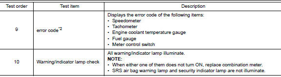
NOTE: When the trip reset switch is pressed during the indication of Test order ŌĆ£10,ŌĆØ test item returns to Test order ŌĆ£2.ŌĆØ
*1: Color Check
- Blue
- Red
- Pink
- Green
- Light blue
- Yellow
- White
- White
- Black
- Light blue
- Black
- Pink
- Black
- Blue
- Black
- Dark blue
- White
- Blue
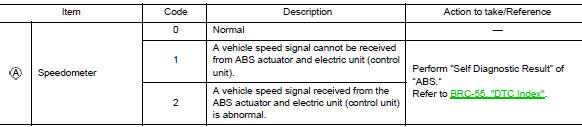
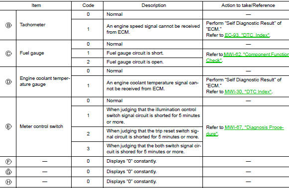
*2: Error Code
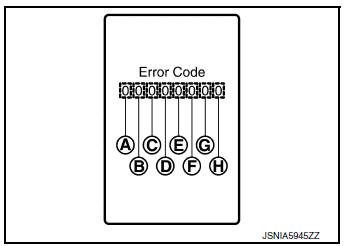
How to Reset Error Code
Error codes stored in combination meter can be reset by following the instructions below:
- Turn ignition switch OFF.
- While pressing the trip reset switch, turn ignition switch ON.
- Keep the trip reset switch for 1 seconds or more.
- Press the trip reset switch at least 3 times. (Within 7 seconds after the ignition switch is turned ON.)
- Turn ignition switch OFF.
- Perform self-diagnosis and check that the error codes are reset.
CONSULT Function (METER/M&A)
APPLICATION ITEMS
CONSULT can display each diagnostic item using the diagnostic test modes shown.
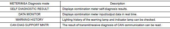
SELF DIAG RESULT
Refer to MWI-30, "DTC Index".
DATA MONITOR
Display Item List
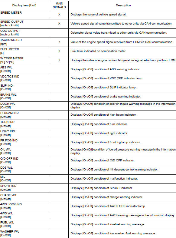
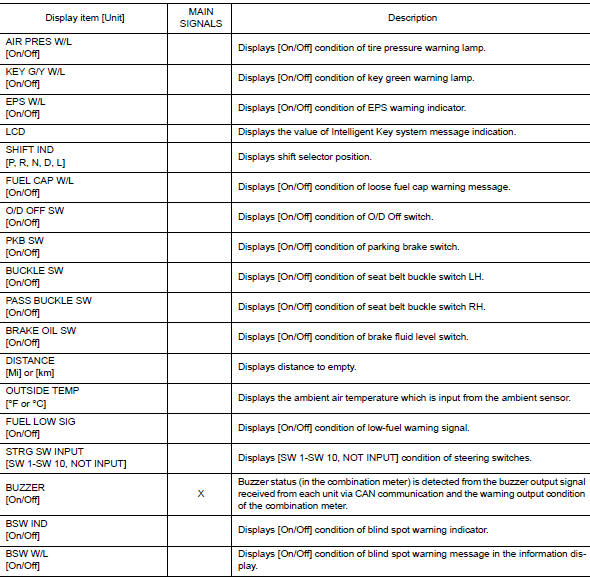
SPECIAL FUNCTION
Special menu

W/L ON HISTORY
- ŌĆ£W/L ON HISTORYŌĆØ indicates the ŌĆ£TIMEŌĆØ when the warning/ indicator lamp is turned on.
- The ŌĆ£TIMEŌĆØ above is:
- 0: The condition that the warning/indicator lamp has been turned on 1 or more times after starting the engine and waiting for 30 seconds.
- 1 - 39: The number of times the engine was restarted after the 0 condition.
- NO W/L ON HISTORY: No warning/indicator lamp history is stored.
NOTE:
- W/L ON HISTORY is not stored for approximately 30 seconds after the engine starts.
- Brake warning lamp does not store any history when the parking brake is applied or the brake fluid level gets low.
 System
WARNING CHIME SYSTEM
WARNING CHIME SYSTEM : System Description
SYSTEM DIAGRAM (WITH INTELLIGENT KEY SYSTEM)
SYSTEM DIAGRAM (WITHOUT INTELLIGENT KEY SYSTEM)
COMBINATION METER INPUT/OUTPUT S ...
 Diagnosis system (BCM) (with intelligent key system)
COMMON ITEM
COMMON ITEM : CONSULT Function (BCM - COMMON ITEM)
APPLICATION ITEM
CONSULT performs the following functions via CAN communication with BCM.
SYSTEM APPLICATION
BCM can perform the ...
Other materials:
Removal and installation
AUDIO UNIT
Exploded View
Audio unit bracket (LH)
Audio unit
Audio unit bracket (RH)
Removal and Installation
REMOVAL
Disconnect the negative battery terminal. Refer to PG-75, "Removal
and Installation (Battery)".
Remove A/C switch (AUTOMATIC AI ...
Rear bumper
Exploded View
Rear bumper fascia side bracket
(LH)
Rear mud protector
Rear bumper reinforcement support
(LH)
Rear bumper fascia undercover
(LH)
Rear bumper reinforcement
Rear energy absorber
Rear bumper bracket (LH)
Rear bumper fascia
Rear bumper fascia re ...
Wiring diagram
POWER DOOR LOCK SYSTEM
Wiring Diagram
INTELLIGENT KEY SYSTEM
Wiring Diagram
AUTOMATIC BACK DOOR SYSTEM
Wiring Diagram
HOMELINK UNIVERSAL TRANSCEIVER
Wiring D ...
